So, we’re doing this mesh thing.
Mesh networks are pretty cool, but stuff tends to get a bit clunky on the hardware side when the need arises for propagating data from the mesh network to the outside world. It is, of course entirely possible to go out and purchase a commercial gateway of some sort. However, this can be both expensive in terms of integration complexity and also frustrating, because of the need to deal with other people’s code and design choices. Things also tend to get a bit proprietary at times.
And this gateway thing.
A gateway basically serves as a bridge between two separate network infrastructures. It has to seamlessly integrate with both networks and be able to transport data and or control messages between them. It should also be invisible from the perspective of the networks that it bridges.
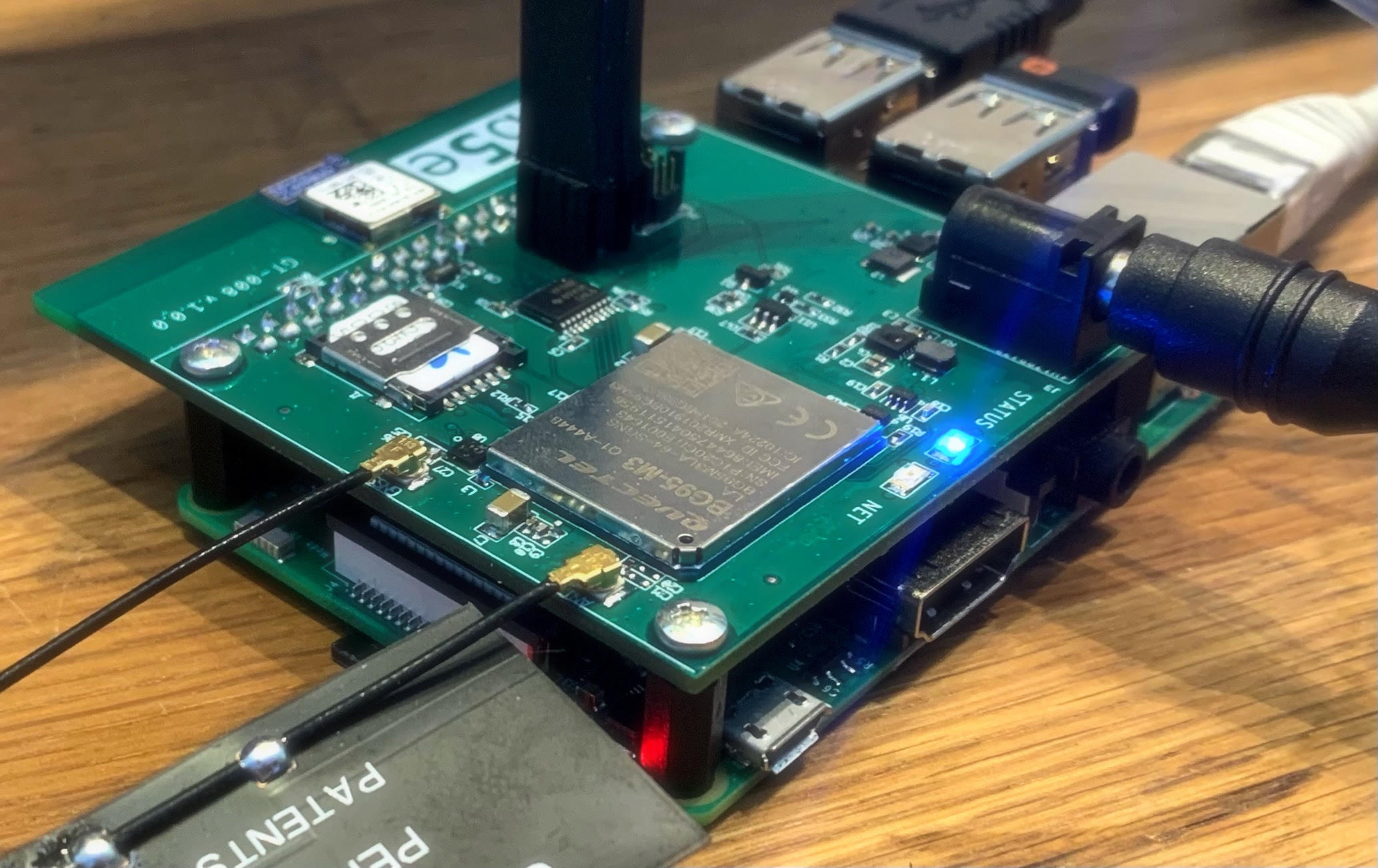
I decided to design my own gateway as a Raspberry Pi shield. A nRF52840 based Bluetooth module will run mesh firmware. This will be able to communicate with the mesh network via Bluetooth and act as an I2C or SPI slave for the Pi. A BG95-M3 LTE module on the same board will be able to send and receive messages over the mobile network and also talk to the Raspberry Pi over UART. In between these two sits a Raspberry Pi that acts as a host processor that can do housekeeping tasks and also coordinate traffic between the mesh network and the mobile network. The Pi also has wi-fi and wired ethernet capability, but the main concern in this use case is being able to forward mesh messages over LTE and also being able to distribute firmware updates to the mesh nodes via LTE.
We’re not running Thread / Open Thread in this case, but I decided to do some basic future-proofing by wiring this thing up with the exact same GPIO mapping that Nordic Semiconductor use in their Thread Border Router example. It can’t hurt and if I’m lucky, the gateway will be able to act as a Thread Border Router without any hardware changes. In theory it should work :)
Which brings me to my point.
Stuff that (in theory), just should work,
that is.
The Pi communicates with the LTE modem over UART. UART communication is probably the simplest serial protocol out there. One just has to connect the RX pin on one end to the TX-pin on the other end and vice versa (or TX to TX and RX to RX if you are running telco equipment - Don’t ask…), specify the correct baud rate, word length, stop bits and parity and voila! You have a connection. It either works or it doesn’t.
I always assume that I make mistakes in designs. It doesn’t require especially many facepalms before you realise that it is a really good idea to always run DRC/ERC-tests before sending a design over to a PCB house for manufacturing. In addition to this I manually inspect schematics, layout and footprints before ordering PCBs. Still - I always worry that there is some little ugly detail somewhere that I haven’t considered or made a note of at some point and then forgot about.
In the case of this gateway, I have 8 pages of schematics, multiple layout restrictions, 4 different power domains and three different antenna paths to worry about.
PCBs in hand, I usually start out testing by checking for any obvious shorts between power domains and ground after I have populated the board. I then connect a lab power, throttled way down on the current side (and also with the least amount of other, potentially expensive stuff connected to the thing I am testing). I then verify that the voltages are correct when measured on the PCB.
If nothing starts to smoke, I move over to flashing firmware (since the board in question usually sports a microcontroller of some sort) and hooking up a JLink debug probe.
With firmware onboard, I can then move on to functional testing. In this case, I needed to verfiy the correct behaviour of various IO pins, like enable signals for the LTE modem and LNA RF frontend for the GNSS, SPI Chip Select, MISO, MOSI, CLK signals etc.
In this case:
- All power domains were in the correct range.
- Programming and debugging via JLink worked like a charm.
- SPI worked like charm.
- The SIM card interface worked like a charm.
- GNSS worked like a charm.
- And - The UART worked like a charm…
Well, - not really.
The UART worked really well after each reboot and then it locked up after some short random interval. The only way to get communication up and running again was to do a hard reset of the modem. I tested with picocom and minicom from a shell on the Pi. After a while, echoes on the terminal varied from nonexisting to raging storms of repeated ASCII input. After a while the terminal usually died, complaining about reading NULL from the other side.
Needless to say. This was a concern. Without stable LTE connectivity via the UART, this gateway shield was just a really big and clunky mesh node - with a Raspberry pi on top.
I started searching for a potential culprit (avoiding any mirrors in the vicinity).
This behaviour could potentially be caused by intermittent voltage drops below the 3.6V limit required by the LTE modem. It could also be caused by electrical noise on the TX/RX lines. The behaviour was way too predictable to be caused by a bad solder joint. It could, of course, be caused by gremlins.
Hooking up a scope to the 3.7V power didn’t reveal anything. TX/RX-lines were wired correctly. Baud rate, word length, parity and stop bits were defined correctly.
I did notice one thing. I measured 1.7V on the RX line at times. Halfway between logical 0 (0V) and logical 1 (3.3V). This was weird.
Ghost in the machine
I truly believed that I had configured everything correctly. The necessary changes in /boot/config.txt are pretty simple (You can read more about the device tree boot overlays here).
[all]
# use UART0 (first PL011) as primary UART
enable_uart=1
# Switch Pi3 Bluetooth function to use the mini-UART (ttyS0) and restore
# UART0/ttyAMA0 over GPIOs 14 & 15.
dtoverlay=pi3-miniuart-bt
# Disable onboard Bluetooth on Pi 3B, 3B+, 3A+, 4B and Zero W, restoring
# UART0/ttyAMA0 over GPIOs 14 & 15.
dtoverlay=pi3-disable-bt
Looking at the serial devices, everything looked fine and dandy.
pi@raspberrypi:~ $ ls -l /dev/serial*
lrwxrwxrwx 1 root root 7 april  8 18:59 /dev/serial0 -> ttyAMA0
lrwxrwxrwx 1 root root 5 april  8 18:59 /dev/serial1 -> ttyS0
It turns out that I probably shouldn’t have ignored the mirror when searching for the culprit that caused the UART instability. Instead of taking the Leeroy Jenkins approach to configuration, I maybe should have forced myself to read through the official UART configuration docs at raspberrypi.org - a few more times.
However, it is IMHO virtually impossible to read through this documentation in its entirety without triggering the onset of an intense urge for a more informative detour through Stack Overflow instead. The documentation is confusing, to say the least.
After repeated read-throughs, I’m left with these main takeaways:
- “You probably want to use a real UART, not just a mini-UART with a reduced feature set”
- “The UART you want is already spoken for”
- “The TXD/RXD pins are mapped to a UART you don’t want them mapped to by default”
- “There are primary and secondary things”
- “It is somewhat unclear if these things are uarts”
- “There are symlinks to things which may or may not link to the actual things that you are looking for”
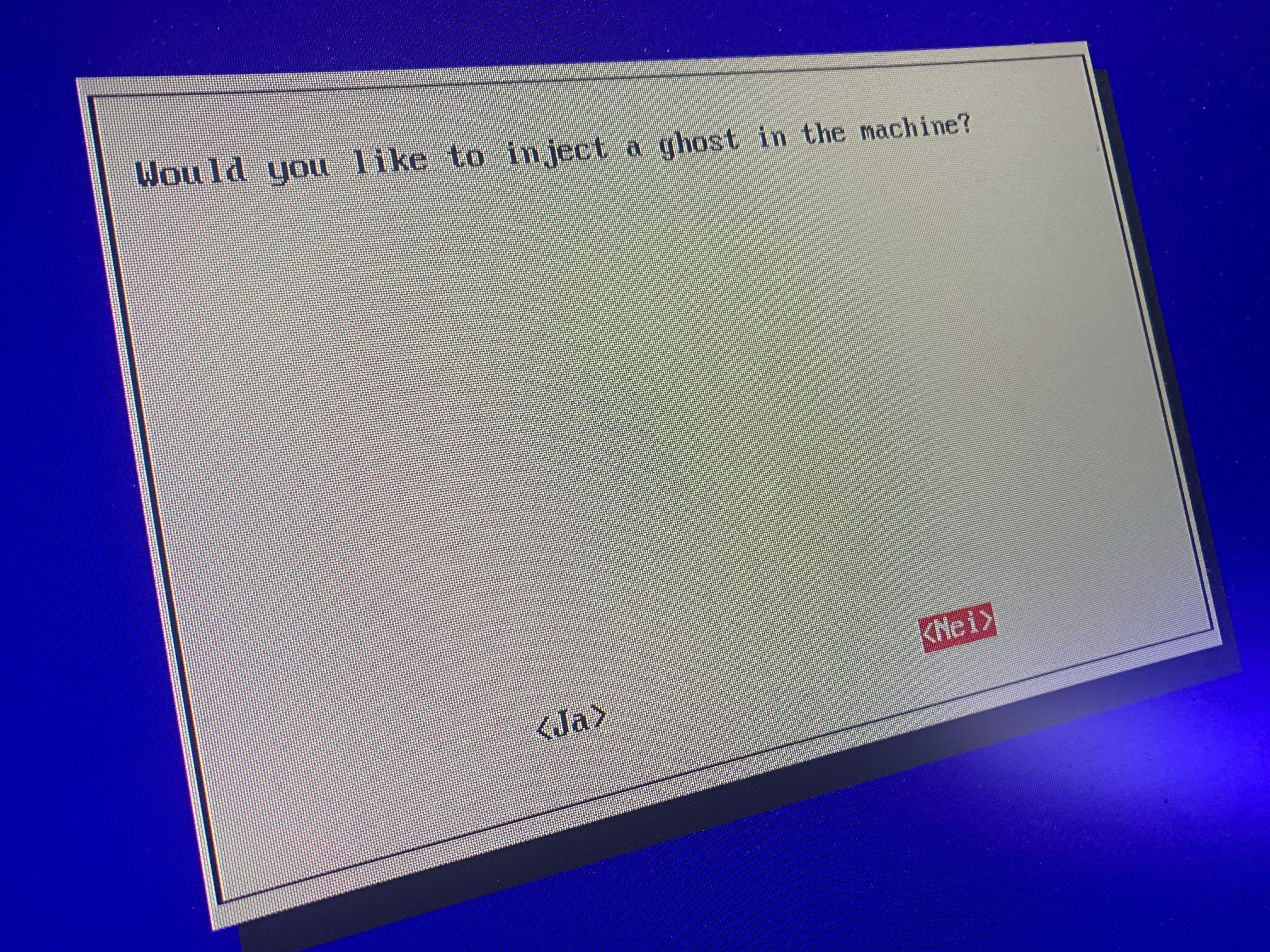
- “You should answer “no” to things.
I’m guessing that most people who land on this official UART Configuration page aren’t that interested in taking a tour of the Linux kernel or are especially interested in popping the hood of the Broadcom chipset for a quick peek inside. They most likely have a really cool UART speaking device that they want to hook up to their Raspberry Pi and test. Two signals. Two wires. Throw in a common ground. Maybe run a terminal emulator or wiringPi. It should be that easy.
The winning recipe
As it turns out. The ghost in my beautiful machine was caused by me not saying no - to things in raspi-config, instead of attempting to edit the boot config options directly. The ghost was just a login shell that was competing with my code for access to the UART. Commenting out the following line in /boot/cmdline.txt solved the problem.
#console=serial0,115200 console=tty1 root=PARTUUID=da818471-02 rootfstype=ext4 e
levator=deadline fsck.repair=yes rootwait
It is never a good idea for multiple interested parties attempting to access the same hardware peripheral at the same time.
Bleeding obvious, I know. Embarrassing, I know.
Further future-proofing
I have now patched raspi-config and am considering creating a pull request for the necessary changes in the serial port interface options menu.