
The Exploratory Engineering team is in documentation mode these days. We have created a working device, but we also have to create reference documentation and tutorials before it can be released.
We already know that our EE02 module is physically small (approximately 30% smaller than a LoPy module). We also know that it extremely power efficient (The EE02 could theoretically be in standby mode for 120 years - using the capacity of two AA batteries). When receiving data, the power consumption is half of what you can expect from a light emitting diode. When it transmits data - only twice as much.
What you probably didn’t know was that the EE02 also has real range. I know the theoretical specifications, but the proof is always in a real, working device - not in a white paper.
We have played with these devices around the office, but this time I decided to hook it up at home for a real test.
My house is located approximately 1800 meters from the gateway. To complicate things further, I decided to do the test from my basement. Given x-ray vision, I would have to look through 3.5 meters of soil, a reinforced concrete floor, a car, several houses and a hilltop (with even more houses) before I could see the gateway.
The test was rather successful. The stamp sized, 3.3V EE02 module connected to the gateway and successfully transmitted data, which in turn could be viewed in a widget in Cloud Connect. This is well within the expected range of 2km in an urban environment, but I was still impressed. We are not even using the full potential of the SX1276 radio chip. The current device is limited to 14dBm output power. Future versions could take advantage of the 1276’s boost option, where it outputs up to 20dBm. The 6dBm difference translates to doubling the range from 14 dBm.
Anyway…
The basement sofa test gave me an idea for a new device.
IoT is all the rage at the time, but what’s the use of an IoT device if you can’t reach a gateway ? How can you know if you’re in range before you invest time and effort in building and deploying stuff ? And last, but not least. Where should we add new gateways in order to insure good coverage ?
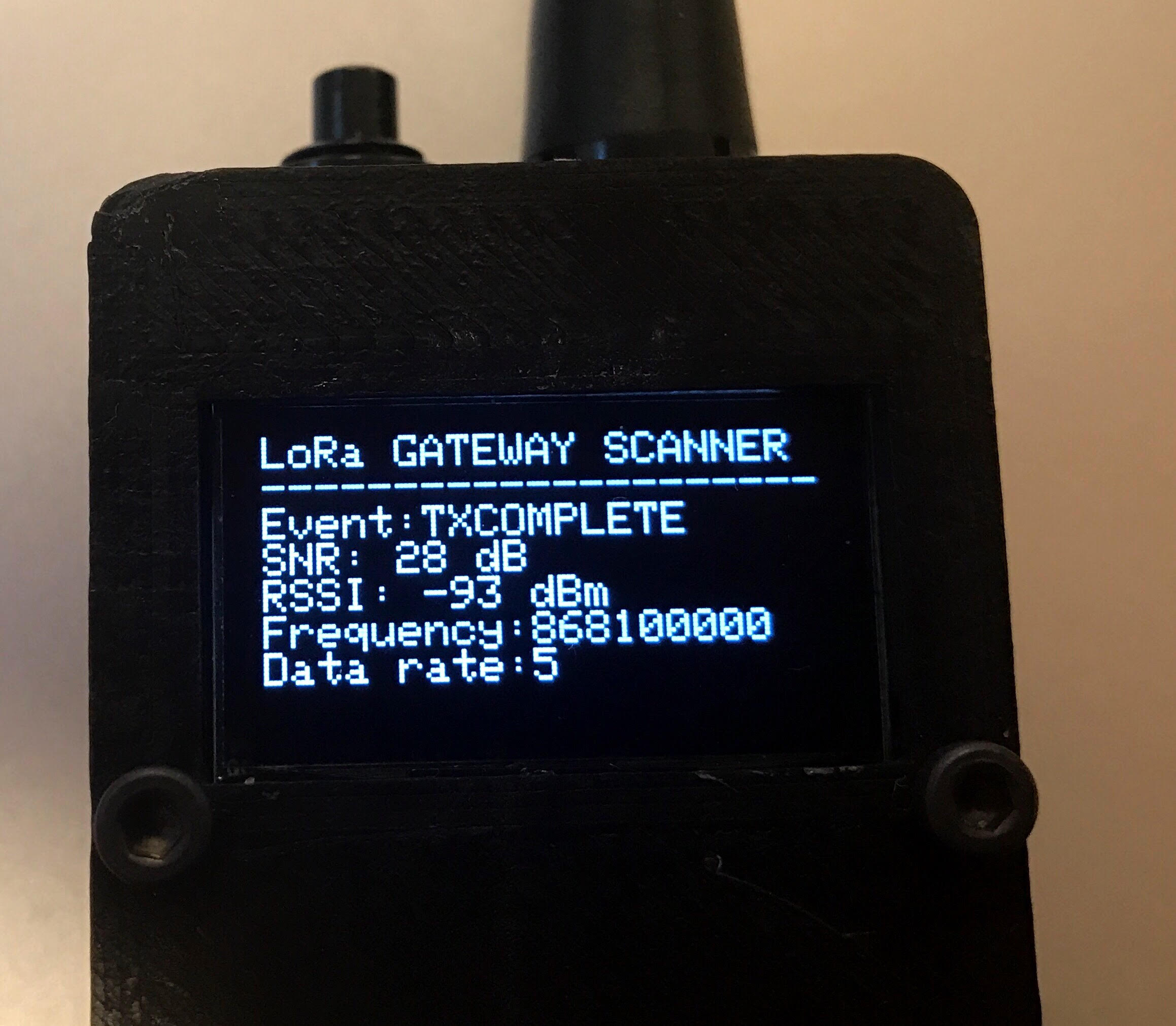
It would be really cool if we could put together a device that was small enough to be carried around in a pocket or a laptop bag. A device that would attempt to connect to the network and then give you information about received signal strength, signal to noise ratio etc.
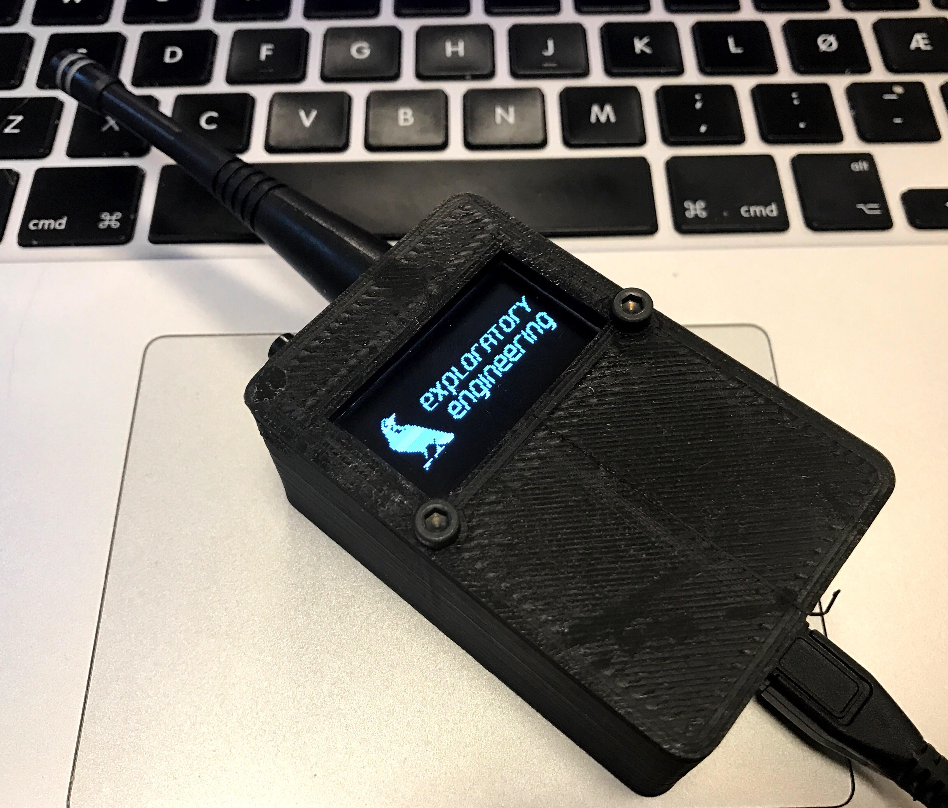
The “LoRa Gateway Scanner”
I decided to use one of the EE02 modules we had lying around the office. I had already assembled some unofficial breakout boards for the module. This breakout exposes all GPIO pins, so it is easy to experiment with. The OLED display is pretty easy to interface (electrically…) and can be controlled via I2C or SPI and a dedicated reset pin.
All the parameters we are interested in are already available via the LMIC library that is used in the current EE02 firmware. Ideally, these should be sent back, along with the corresponding GPS coordinates.
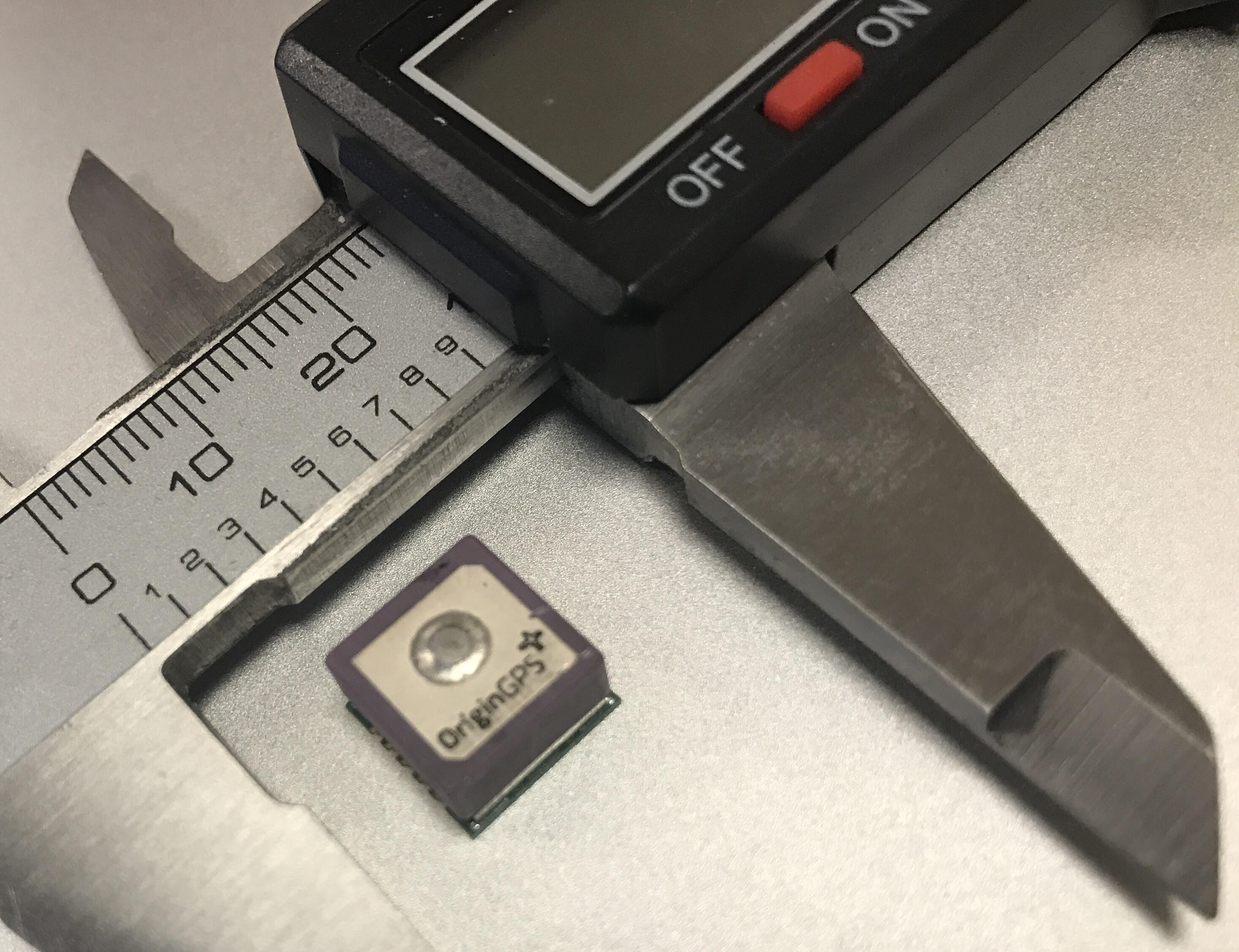
I decided to start prototyping. I had access to Origin GPS modules, but since I didn’t have a breakout PCB for them, I decided to start with a “Minimum Awesome Product” and use a small OLED display to show LoRa events, SNR, RSSI etc. I ordered a couple of displays, along with 868MHz antennas and a couple of buttons from DigiKey. I had never interfaced to this type of display before. How hard could it possibly be ?
Well…
It turned out to be pretty hard. Even with access to sample code and tutorials, I had to spend a full day (and most of the evening) before I was able to control the OLED display. After checking if the display used internal pull-up resistors and verifying correct behaviour for the reset line, I finally figured out that the “no stop” parameter in the nrf_drv_twi_tx call couldn’t be trusted when talking to this display. After sending the I2C register address together with bytes to the framebuffer, I had a working display. Yay !
That is, I had a working graphical display. Since I needed to display text, I also had to write some code that implemented a text buffer that could be written to from the lora_job. A dedicated display job would then do the necessary bit-blitting by looking up font bitmaps in an array and then transferring these to the graphical frame buffer. This took me another day.
(Yes, I know that Adafruit has published a graphics library for this module, and that it probably would have worked just fine with ug8lib, but doing stuff from first principles is good for you.)
Time to assemble the physical stuff !
After taking some measurements of the PCB, display and antenna, I had enough information to make a 3D model of the enclosure in Autodesk Fusion 360. This took the best part of an hour. The first enclosure didn’t fit too well, so I had to adjust the model and do a second printing. Total printing time: 3 hours.
The LoRa Gateway Scanner could now be assembled into a working device.
Parts list
- EE02 module + breakout
- 128x64 monochrome OLED display with SSD1306 driver.
- 868MHz antenna.
- Fancy button. (The button doesn’t really do anything (yet), but it makes a really nice clicking sound when you press it.)
- Two 16mm M3 screws.
Next versions
- I’ll try to hook up an Origin GPS module for the next version, but I will probably have to make a small GPS shield for the unofficial EE02 breakout, since the GPS module is relatively small.
- Find a use for the button.
Links
- More or less coherent code fragments can be found at: https://github.com/telenordigital/ee0x-firmware/tree/master/experimental/display/ssd1306
- STL files for 3D printing can be found at: https://github.com/telenordigital/ee0x-hardware/tree/master/experimental/Display/Lora%20Gateway%20Scanner