The EE02 is not an end user device. It is a module that is intended as a component in other designs - assembled by machines. Our aim was to fit the design in the smallest form factor possible, while maintaining the desired performance characteristics. This translates to surface mount technology that can be maniupulated by pick and place machines - not people.
But, please…
Don’t panic !
Even though surface mount components are harder to tinker with than through hole components, it is entirely feasible for makers and hobbyists to make their own printed circuit boards without having to invest significant amounts of money and effort. Expect to spend a few hours learning how to navigate an electronics CAD package. Other than that, your investment is limited to component cost and PCB manufacturing. There are several manufacturing houses that will produce a batch of 10 prototype boards for you for less than 30 USD, including shipping. Expect a turnaround time of 1-2 weeks for a protoype batch.
EE02 was designed using Altium, which is a professional electronics CAD program. It is powerful and relatively expensive. Fortunately, there are also many free/low cost alternatives out there. Some examples are Eagle, KiCAD and Target3001. These have less advanced feature sets than Altium, but they contain everything you will need in order to make a two layer circuit board. I have personally used Target3001, but later decided to switch to Eagle, since this seems to be the CAD package of choice for most makers and hobbyists.
Designing your circuit
A basic understanding of electronics is all you need to get started. If you know ohm’s law and have access to a soldering iron, you’re golden.
In this example we are going to make a simple CO2 sensor board. The board will host only a few components. We will start with:
- An EE02 Module. This has an onboard microcontroller and a radio chip.
- A CO2 sensor that is easy to communicate with. We will use the AMS iAQ-core in this example.
- A programming socket for connecting our board to the nRF52 development kit. For simplicity’s sake, we’ll select the same socket that is already used on the debug out connector on the nRF52 development kit (J19).
- A power connector. We’ll use a USB micro connector, since this enables us to power our board with everything from phone chargers, to power banks.
When selecting components, you have to make sure that they are compatible with each other. You can make 5V devices talk to 3,3V devices, but it will simplify the design if everything can be powered with the same supply.
The EE02 can run on voltages between 1.8 and 3,6V. The iAQ-Core sensor datasheet specifies 3,3V. We should therefore use 3,3V for internal power, since this is a voltage that is compatible with the requirements for both devices.
Since USB power is 5V, we will have to somehow convert this 5V source down to 3,3V. This is done by inserting a component called a voltage regulator between our power connector and the rest of the circuit. In this example we’ll use a LM1117 regulator. From it’s datasheet we see that this can handle input voltages of up to 20V. It can also handle currents of up to 0,8A. It’s overkill for our purposes, but since I’ve got a drawer full of them it’s what we are going to use. From the datasheet we see that it requires two additional capacitors. We will extend our parts list with the following components:
- LM1117
- 10 uF Tantalum capacitor
- 100 uF Tantalum capacitor
Components can be sourced from all major electronic component distributors, such as DigiKey, Mouser, Farnell, RS etc.
Ok, I have sourced all my components and I’m itching to go. How do I start ?
- Download and install an electronics CAD package. We’ll use Eagle in this example.
- Create a new project by opening the Eagle control panel and selecting “Projects/Eagle” in the sidebar. Right click on “Eagle” and select “new project”. Give it the name “CO2Sensor”. Right click on the project and select “New/schematic”. Schematic view will open and we are (almost) ready to go.
- Download the EE Eagle library and copy it to Eagle’s LBR folder. This library contains symbols and package footprints for the components we are going to use.
- Switch to the control panel window and expand “libraries” in the sidebar. Navigate to “EE” and expand this node. You will see a list of components. If you double click on a component, Eagle will switch to schematic view, allowing you to place the component in the schematic. Repeat this procedure for the following components (You can move them around later if you wish):
IAQ-COREEE02_O2DEBUGHEADERUSB_MICRO_BLM1117
If you can’t find a specific component in one of the libraries, it is very easy to define your own symbols and packages in Eagle. You will find all necessary information in the component’s data sheet. First, you will have to create a schematic that describes how all the components are connected. Each component will have a symbol, a name, a value and a number of pins that represents power, ground, inputs and outputs. Passive components have standardized symbols. This makes schematics easier to read, but there’s nothing preventing you from creating a symbol in the shape of a banana for a given component. Just sayin’ ;)
After having placed our components, the schematic will look something like this:
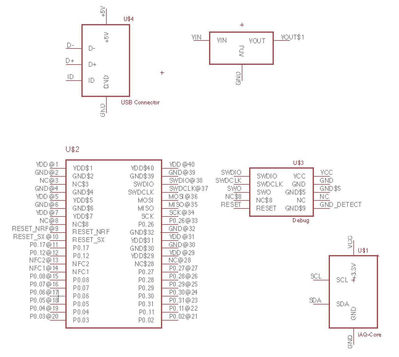
Power and ground.
Power and ground are special symbols that are not associated with components. We will use them only to indicate which nets the power and ground pins on our components will be connected to.
- Open the control panel again and expand “Libraries” in the sidebar.
- Navigate to the “Supply1” library and expand it. A list of voltage and ground symbols will appear.
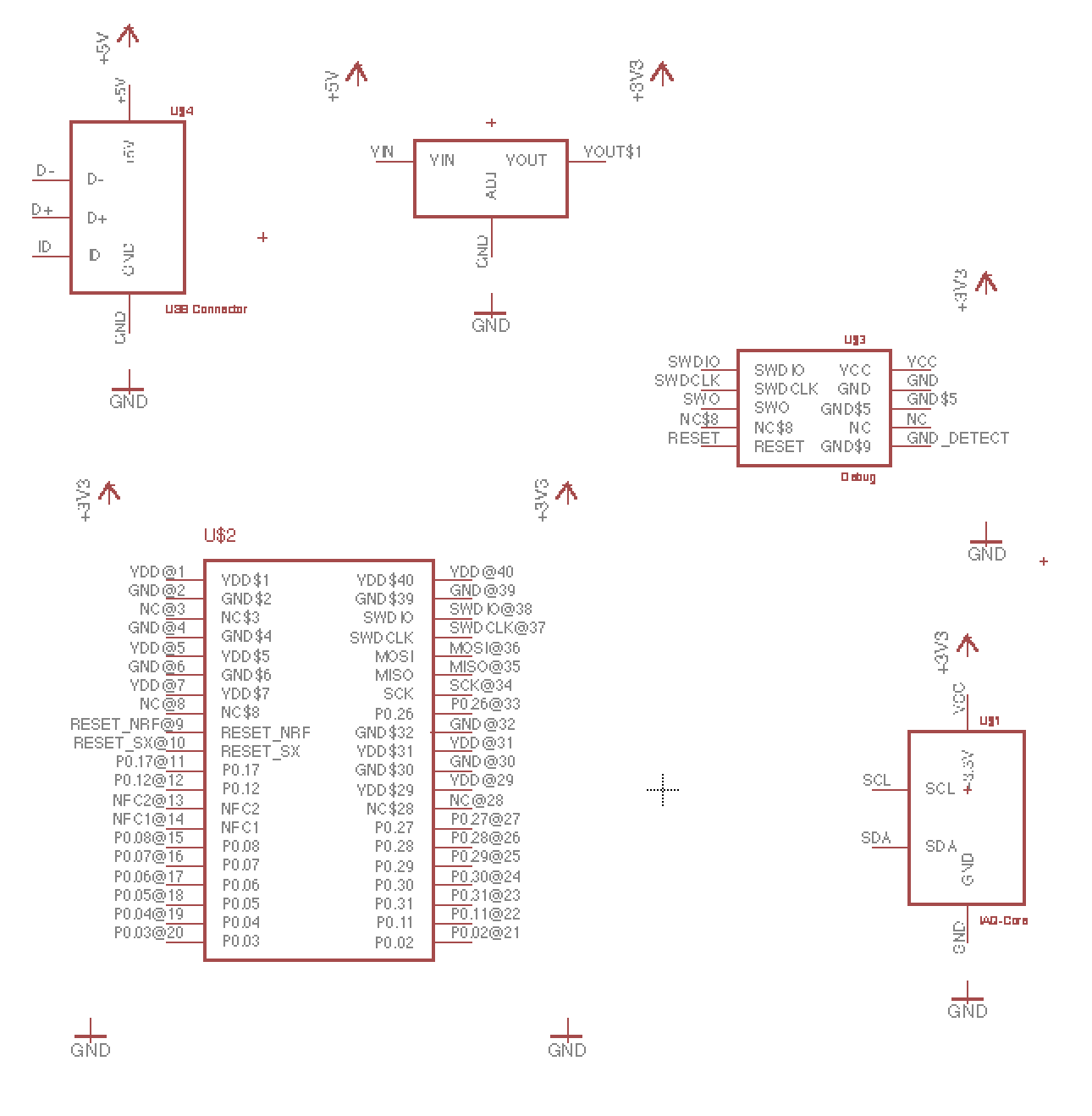
- Drag a ground symbol (“GND”) to the schematic and plane one underneath each of our components (Two for EE02). We could use only one, but it would make our schematic messy when we later connect everything toghether.
- Drag a +5V symbol and place it above the USB connector symbol. Also place one above the regulator symbol (on the left hand side).
- Drag a +3.3V symbol and place two above the EE02. Also place one above the debug connector, the sensor and above the regulator (on the right hand side).
If you need to move stuff around in order to make room for everything, you can right click on a symbol and select “Move”
Your schematic will now look something like this:
Your first nets
- Type “NET” in the text edit control box that sits just above the schematic area. Press enter. You can now start connecting stuff together.
- Select the end of each power symbol and connect it to it’s corresponding pin on the nearest component symbol.
- +5V to +5V on the USB
- +5V to VIN in the regulator.
- +3.3V to each of the VDD pins on the EE02.
- +3.3V to the VCC pin on the debug header.
- +3.3V to VCC on the sensor.
- Connect all ground pins to a ground symbol.
- Also connect the GND_DETECT pin on the debug connector to a ground symbol.
Use the NET command to connect pins together.
We will ignore the data pins on the USB connector since we are only going to use +5V and ground. Everything now has power and ground, but We still have to connect the debug header and sensor to the EE02.
- Use the net command to connect SWDIO on the debug header to SWDIO to EE02.
- Do the same for the SWDCLK pins.
- Connect the SCL pin on the sensor to pin P0.28 on EE02.
- Connect the SDA pin on the sensor to pin P0.29 on EE02.
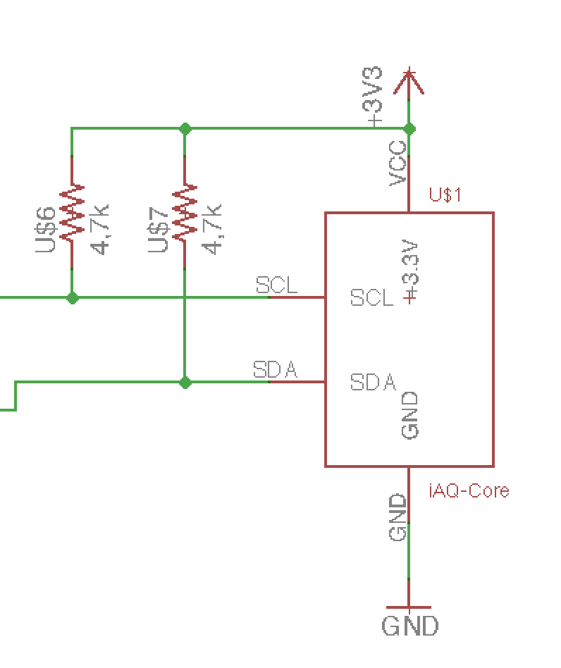
Your schematic will now look something like this:
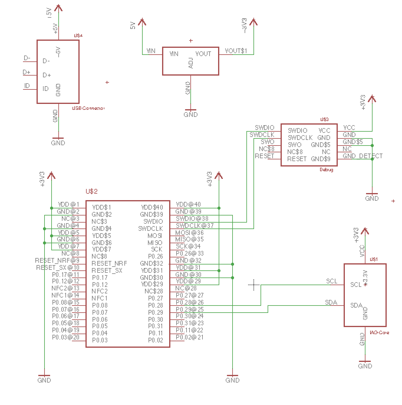
We have connected 5V from the USB to the input of the regulator. The +3.3V output of the regulator is connected to the VDD/VCC on all the other component. Everything has a ground reference. The I2C lines (SDA/SCL) on the sensor is connected to two GPIO pins on the EE02 and the programming (debug) header is connected to the correct pins on EE02.
It’s looking good. Right ? Yay… ?
Nope. Now is time to experience the classic moment in everything design related. Namely the …
“Doh !” experience.
Doh! moments are to be expected. Embrace them. They are a source of learning.
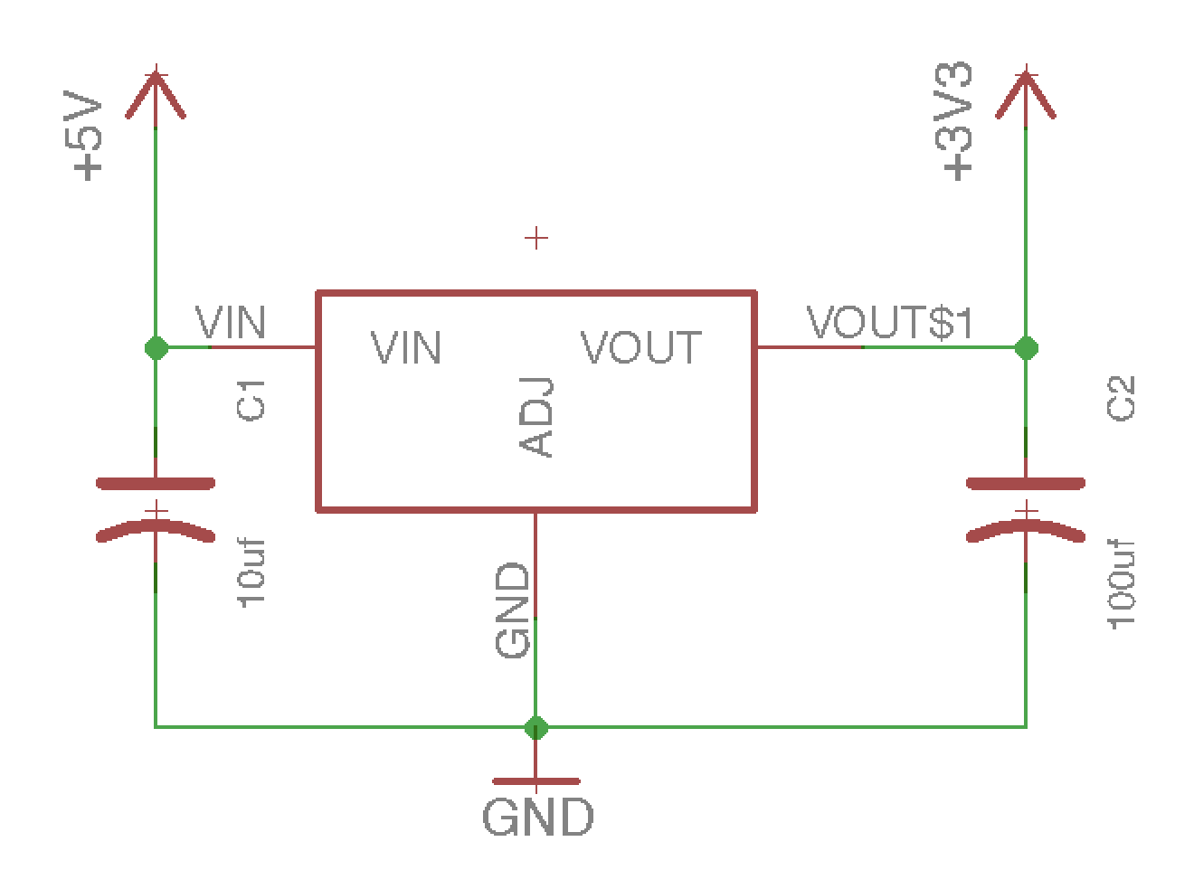
The LM1117 data sheet has a typical application circuit example. This contains two capacitors - that we forgot to add. We need to find two capacitors that we can add to our design. What we need are symbols for polarized capacitors (tantalum capacitors are polarized) that also has a package that suits us. (0805 or 1206 packages are ok, since they are big enough to hand solder)
- Open the control panel again and right click on “Libraries” in the side bar.
- Right click and select “Search in folder”.
- Type “tantalum-smd-10uF-20V” in the search text box and press “next”.
- Right click on the component and select “Copy to library” (Don’t worry about the value. We’re going to use it as a template only. We need the symbol and the package.)
- You will now find this capacitor in the EE library. Click on it and create one instance on each side of the regulator in the schematic. Right click when placing the capacitor in order to rotate it. The curved line should face the Gnd symbol.
- One capacitor should be on the VIN side and one on the VOUT side. Connect each to their corresponding V IN/OUT and both to ground.
- Right click on the rightmost capacitor and select “properties”. Type in “100uf” in the value field.
We now have a working regulator. I assume you have spotted the second mistake ?
We are going to use the I2C protocol to communicate with the sensor. This is a two wire interface that has a clock line (SCL) and a data line (SDA). The I2C master will control these lines by pulling them low when transmitting a logical “0”. It will not pull them high for a logical “1”. This is the responsibility of two pull-up resistors that connect each line to (in this case) 3,3V.
Even if some devices have internal pull-up resistors, you probably don’t know the power on / sleep state of these or their strength. It is good practice to use external pull-up resistors for I2C.
- select a resistor in the EE library. Any 0805 / 1206 will do. We’ll change the value once they are placed in the schematic.
- Change the value of both resistors to 4k7
- Connect the end of one resistor to the SCK line and the end of the other to the SDA line.
And you’re done !
Well, almost…
We still don’t have a PCB. We have only created a simple schematic.
- In the “File” menu. Select “Switch to board”.
- Eagle will ask “Create from Schematic” ?
- Answer “yes”
You will now see the package footprints of your components and the pins of those components connected as a “rat’s nest” next to an empty board area.
- Right click on a component, select “move” and drag it onto the board area.
- Repeat for all components until you are happy with the placement.
- In order to adjust the board area, right click on a board edge and select “move”.
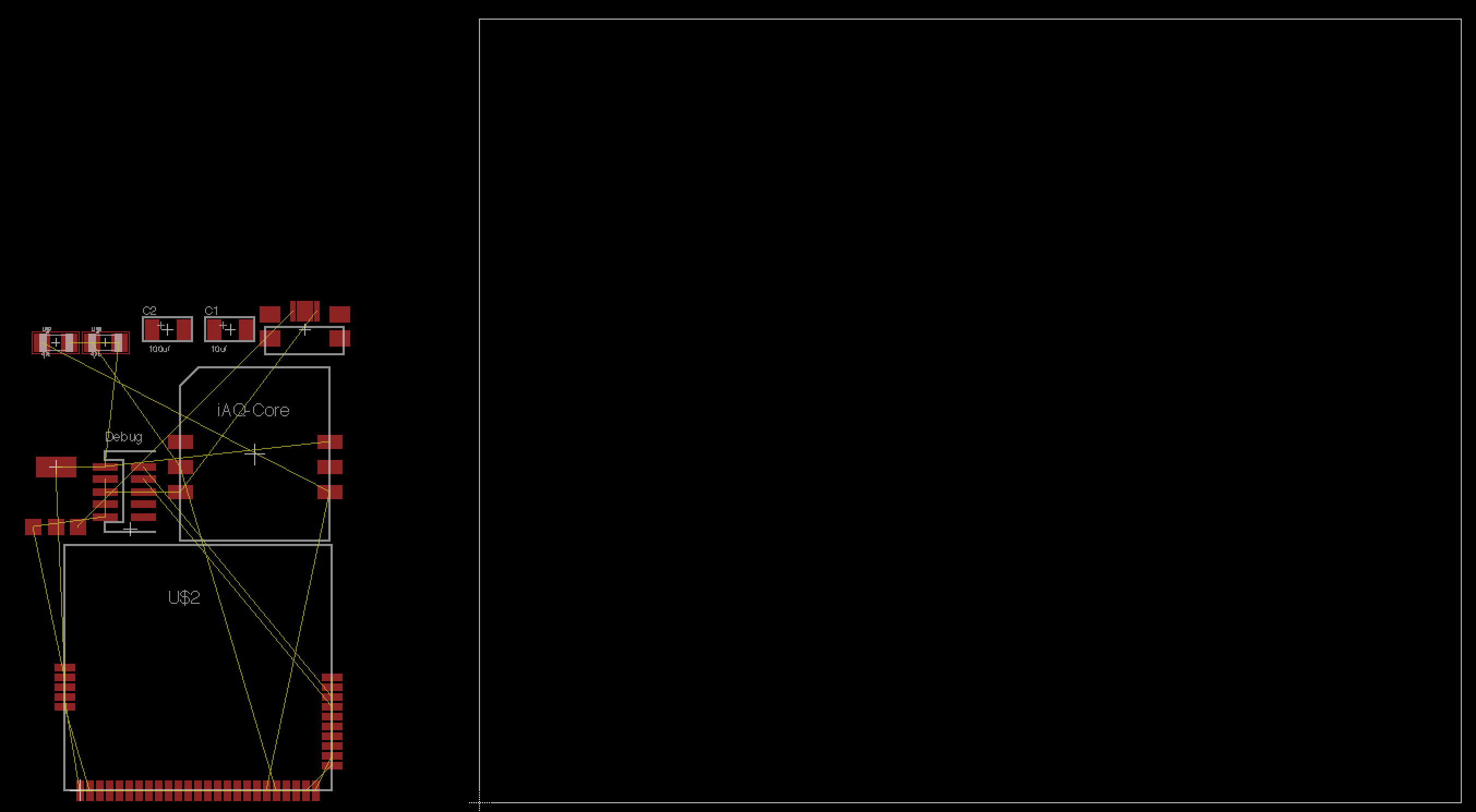
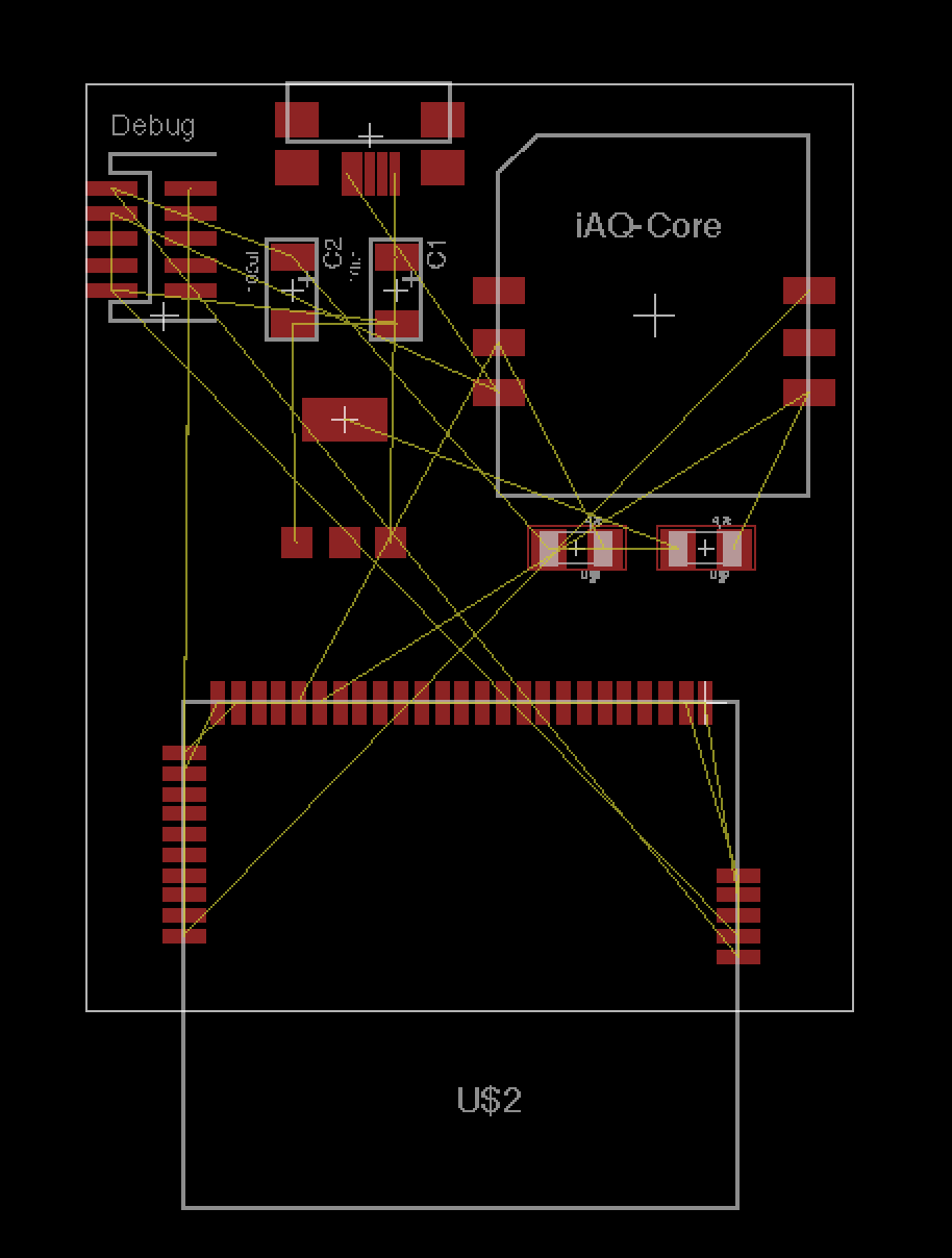
You may end up with something like this:
It is still a rat’s nest. Traces have to be routed. These can (and probably should be) routed manually, but you can also use the autorouter.
- Select “Autorouter” from the “Tools” menu.
- Select “High” in the “Effort” drop down.
- Press “Continue”.
- The autorouter will now display a window displaying multiple alternatives.
- Press “Start”.
After it has finished, you can select one of the 100% finished alternatives. The result from the “Top Router” is usually a good choice.
- Select an alternative and press “end job”.
- Save the board.
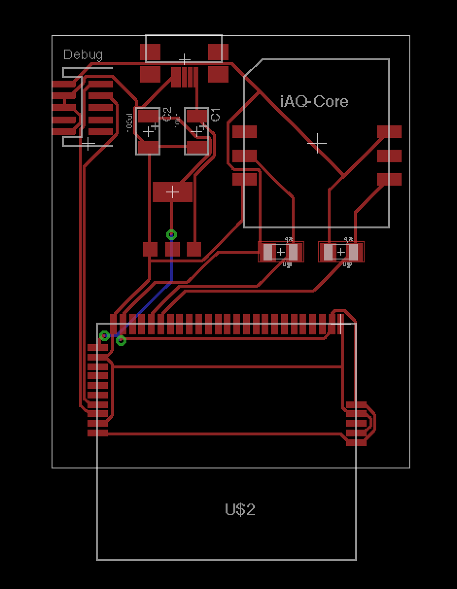
Gongratulations ! You have now created a (hobbyist level ;)) PCB !
Ish…
You still don’t have a physical board to play with. Fortunately there are a many PCB manufacturers out there and many target the hobbyist / maker community. An example is DirtyPCBS.com, where you can upload your board file (.brd) and get an instant quote. Select anything but normal air mail and you will recevie your boards in a couple of weeks.
PS. This tutorial may contain errors, but you should be able to use the information to prototype simple EE02 based boards in Eagle by now. Just remember to read the data sheets for any new components thoroughly before designing circuits around them.
I usually don’t get my boards 100% ok on the first attempt. You may have better luck. Happy EE02 hacking ! :)