I guess Ray Kurzweil’s “law of accelerating returns” also applies to small-scale prototype development. My experience has certainly been that the more stuff you build, the faster you can build new stuff - even on a relatively small scale.
I made the GT-004, which is a breakout board for the Quectel BG95-M3 LPWA module a few months back. Except for the Skyworks LNA, and the added support for a wider IO voltage range tolerance it is more or less identical to the Quectel reference design.
GT-004 is intended to be used as a module for enabling rapid IoT prototyping on popular platforms, like the Arduino, the ESP32, or the Raspberry Pi.
From a design perspective, it can also be considered as a functional block that can be added to other, more specialized designs that need support for NB-IoT/LTE-M connectivity.
The Seed
After the GT-004 exercise, I had the opportunity to play around with and familiarize myself with OpenThread for a couple of weeks. This is an open-source implementation of the Thread mesh protocol (released by Google).
My first setup used Nordic Semiconductor nRF52833 development kits as mesh nodes. The CLI (command-line interface) that is available on the nodes lends itself to easy configuration and testing of the mesh. The CLI also nicely mirrors the internal OpenThread API, which means that moving from CLI to a programmatic interface is a pretty smooth exercise.
My OTBR (OpenThread Border Router) was based on the OTBR Codelab. The OTBR configuration uses a Raspberry Pi in conjunction with a USB-connected thread-capable device, such as the nRF52840 DK as a radio co-processor.
Since Lab5e is in the LTE-M/NB-IoT game, I decided to throw my GT-004 into the mix. This worked fine, but there were wires and boards - everywhere. Eventually, one of my hook-up wires broke free (the 3.3V lead) and found a nice piece of unintentional ground somewhere on the Pi. I heard a POP and felt a whiff of burnt Raspberry Pi in the air.
This incentivized me to revisit my old friend, Autodesk Eagle to see if I could design something a bit more “solid-state” that I could play with instead (Yes, I do have an Altium license, but Eagle is for some reason still my favorite goto candidate for small hardware prototypes).
The Raspberry Pi has a nice GPIO header and I had previously noticed that the Nordic Semiconductor version of the OTBR (this can be found in the nRF5 SDK for Thread and Zigbee) had an example setup for communicating with the NCP/RCP over SPI.
This made me go “Hmm…”
Let’s accelerate
The OTBR hardware is basically the sum of a few standard functional blocks that play nicely together through well-defined interfaces. My GT-004 also has a well-defined interface (AT over UART). Why not let it participate?
I set out to make myself an OTBR with a smaller form factor and fewer dangly bits.
The Pi had to stay. That’s a given, but the entire nRF52840 DK could be replaced with just the nRF52840. Well, - kind of. It would still need a Bluetooth antenna and a few support components.
I don’t feel too comfortable messing about too much with antennas, impedance matching, network analyzers, and smith charts. In addition to this, it struck me that the size and pitch of the 73-VFQFN dual row package of the nRF52840 probably weren’t exactly conducive to ending up with a working prototype in a my basement home office lab.
Fortunately, there are alternatives out there that can save you both time and grief in such cases. I decided to try out the Laird BL654. This has a built-in BT antenna and encapsulates the Nordic nRF52840 as well as all necessary support components. It’s still no bigger than a fingernail, but the footprint and pitch are “basement lab friendly”.
The gateway design was finished in a couple of evenings and the CAM files were sent off to AllPCB for manufacturing.
I had decided to keep the pin mapping from Nordic’s OTBR example since this would allow me to run the binary OTBR Pi image unmodified and still have the capability of developing new software on top of that.
We’ll take look at some code later on and I dare you to find any other LTE-M or NB-IoT gateway that provides you with the same ease of development.
(Actually, I would be quite happy to receive any suggestions, since the downside of my design is that it doesn’t come with a fancy enclosure or antennas. It doesn’t have any end device certifications either. The latter is likely a requirement in most settings for use in a commercial application.)
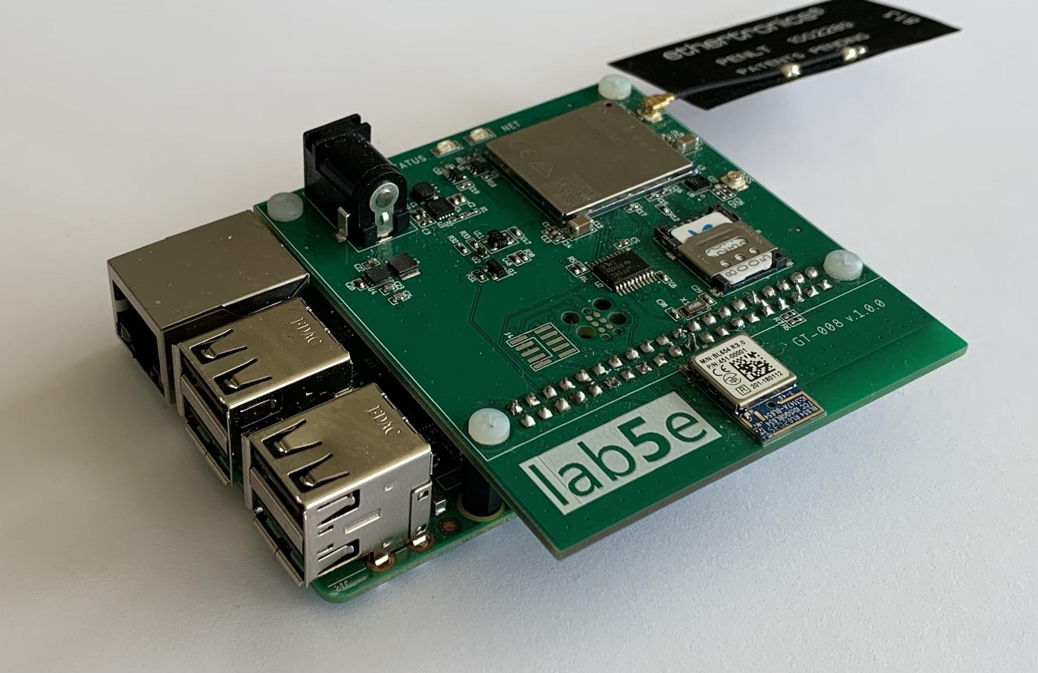
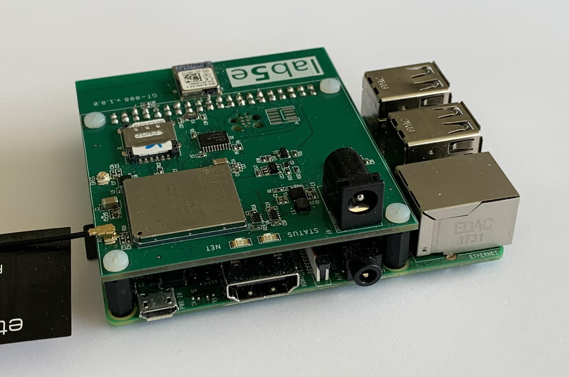
The hardware
This is what I came up with. It’s nothing more advanced than a Raspberry Pi with a GT-004 and an nRF52840 on top, but there are no dangling wires and no shorts. No popping sounds when powering on either.
Both 5 and 3.3V power domains are accessible from the Raspberry Pi GPIO header. It would seem natural to power the gateway shield from these pins. That is - until you start digging around the interwebs to find out exactly how much power you can draw before something goes POP or browns out.
I decided to power the Pi from the shield instead. This bypasses any fuses on the Pi, so performing the initial power-up is quite the sobering exercise.
(I haven’t done any design based on the Nordic Semiconductor nRF9160 yet, but since we already have a few hundred of them in stock, it is quite tempting to design an nRF9160 version as well)
Programming and initial testing
This turned out to be unexpectedly straightforward.
-
The BL654 was flashed with the nrf52840_xxaa_pca10056.hex image located under “examples\thread\ncp\ftd\spi\hex" where I installed the nRF5 SDK for Thread and Zigbee. I used the programmer that is available via the nRF Connect for Desktop application using a Segger J-Link probe connected to the 6 pin programming header I had designed in.
-
I then downloaded the RaspPioT Border Router Demo image from Nordic and wrote that to an SD card.
-
Since I was going to test bridging OT and LTE-M, I only needed one mesh node. I used an nRF52833 DK for this task. This was programmed as a full-thread device. To be able to use the command-line interface for sending UDP test messages, I connected this to my Mac via USB and used Coolterm to access the shell on the mesh node.
The node and the border router was configured with the same defaults, so all I had to do was to match the panid, enable the interface, and start thread via the CLI
> panid 0xabcd
Done
>
> ifconfig up
Done
>
> thread start
Done
And then proceeded to ping 64:ff9b::0808:0808 via the CLI on the nRF52833 node
> ping 64:ff9b::0808:0808
>
> 16 bytes from 64:ff9b:0:0:0:0:808:808: icmp_seq=4 hlim=116 time=47ms
Yay, We got a reply! Time to move on to the next task.
Intercepting mesh messages
I would suggest that the absolute minimum functional requirement for an LTE-M mesh gateway is that it can receive outgoing messages from the mesh and then forward them over LTE-M via the onboard modem.
To do this, we need to know the IPv6 address that the mesh nodes should send messages to. We are interested in the wpan0 interface on the Pi. This is provided by wpantund, which is a user-space network interface driver that provides a native IPv6 interface to the NCP.)
If I open a shell on my Pi and run “sudo wpanctl status”, I can see the following information for the wpan0 interface:
wpan0 => [
        "NCP:State" => "associated"
        "Daemon:Enabled" => true
        "NCP:Version" => "OPENTHREAD/0.01.00; POSIX; Jan 25 2019 13:36:55"
        "POSIXApp:RCPVersion" => "OPENTHREAD/20191113-00534-gc6a258e3; NRF52840; Apr  5 2020 21:51:18"
        "Daemon:Version" => "0.08.00d (; Apr 21 2020 19:11:43)"
        "Config:NCP:DriverName" => "spinel"
        "NCP:HardwareAddress" => [F4CE36357B5454C1]
        "NCP:Channel" => 11
        "Network:NodeType" => "leader"
        "Network:Name" => "NordicOpenThread"
        "Network:XPANID" => 0xDEAD00BEEF00CAFE
        "Network:PANID" => 0xABCD
        "IPv6:LinkLocalAddress" => "fe80::b88d:6631:7a07:b575"
        "IPv6:MeshLocalAddress" => "fdde:ad00:beef:0:54a4:2574:5ced:bc79"
        "IPv6:MeshLocalPrefix" => "fdde:ad00:beef::/64"
        "com.nestlabs.internal:Network:AllowingJoin" => false
]
The following code fragments are written in Python. For the sake of clarity, I am also going to use clear text messages. The following code show how you can write a simple IPv6 UDP listener that will just print out any messages received (sent to the IPv6:LinkLocalAddress shown above). It could just as well have been written in C, Golang, or any other language with socket support.
import socket

UDP_IP = "::"
UDP_PORT = 5005

sock = socket.socket(socket.AF_INET6, socket.SOCK_DGRAM)
sock.bind((UDP_IP, UDP_PORT))

while True:
        data, addr = sock.recvfrom(1024)
        print("received message: %s" % data)
There is no reason we cannot implement two-way communication as well. Span already has support for firmware updates for LTE-M devices. This mechanism relies on COAP over UDP. In practice, this boils down to using the AT command abstractions for UDP sockets that are available on the modem. We could then quite easily implement a mechanism on the OTBR that reports running firmware versions on mesh nodes and checks for any scheduled updates in Span. This is however beyond the scope of this blog post.
Since we now can receive mesh messages, we are in a position to forward them to our modem. Let’s extend the Python program a bit and prepare the necessary plumbing for the Pi UART configuration.
UART Mapping
Disabling the serial login shell and adding the following three lines in /boot/config.txt will provide us with UART access on the TXD/RXD pins on the Pi GPIO header via /dev/ttyAMA0.
enable_uart=1
dtoverlay=pi3-miniuart-bt
dtoverlay=pi3-disable-bt
After a reboot, we can now communicate with the modem from our test code. We will also have to install pyserial to do this.
sudo apt-get install python-serial
Barebone gateway code example
Before we move on. Keep in mind that this is not production code in any way, shape, or form. It is happy-path coding all the way and we don’t check for any errors that may occur. It is a rough sketch that attempts to demonstrate a concept using as few lines of code as possible. It is, however running code.
For the sake of clarity, I have excluded APN and modem configuration from the Python code example below. We first have to power up the modem via the PWRKEY pin (also mapped to the Raspberry Pi GPIO header). The necessary initialization AT commands are:
AT+CGDCONT=1,"IP","mda.lab5e"
AT+QCFG="nwscanmode",3,1
AT+CGACT=1,1
AT+CGPADDR
The first AT command defines our APN and creates a PDP context. The second tells the modem to scan for LTE-M only. The third one activates the PDP context. As soon as the fourth AT command responds with an IPv4 address we are ready to start sending data.
LTE-M Gateway Code
import socket
import serial
import time

UDP_IP = "::"
UDP_PORT = 5005

sock = socket.socket(socket.AF_INET6, socket.SOCK_DGRAM)
sock.bind((UDP_IP, UDP_PORT))

ser = serial.Serial(
        port='/dev/ttyAMA0',
        baudrate=115200,
        parity=serial.PARITY_NONE,
        stopbits=serial.STOPBITS_ONE,
        bytesize=serial.EIGHTBITS,
        timeout=1
)

ser.close()
ser.open()
ser.isOpen()

ser.write("AT+QICLOSE=1\r");
time.sleep(0.5)
ser.write("AT+QIOPEN=1,1,\"UDP\",\"172.16.15.14\",1234,3030,0\r")
time.sleep(0.5)

while True:
        data, addr = sock.recvfrom(1024)
        print("received message: '%s' from %s" % (data, addr))
        cmd="AT+QISEND=1,%d\r" % len(data)
        ser.write(cmd)
        time.sleep(0.5)
        ser.write(data)
Note: The initial serial and socket close calls are examples not to be followed (on how not to code), but it saves me from having to implement error handling or releasing resources. The same goes for the 0.5-second sleep calls. The code just waits until the modem has had time to respond and ignores if it is “OK” or “ERROR”. This results in a smaller code example that is easy to read, but it is NOT an example of how to implement this in a real environment.
Still. It’s kind of cool to implement an LTE-M mesh gateway that runs on 22 lines of Python :)
Demo time
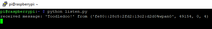
First, we will start our Python script on the Raspberry Pi. We will then move over to the command line shell that we have opened on a mesh node and check the state to verify that it is part of the network. If everything is ok, we will proceed to send a UDP message to the listener port on the gateway.
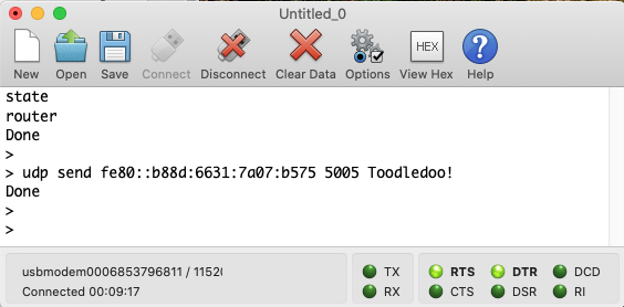
On the SSH shell we have opened on the Raspberry Pi, we can see that a message has been received.
The message should also have been forwarded to Span via the AT+QISEND command. Let us head over there and check.
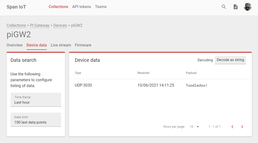
We can see that the message that originated inside the OpenThread mesh network has been successfully routed through the gateway, over the mobile network, and into Span.
Closing comments
We could have taken this one step further and implemented a local client that uses the Span API to retrieve data, but since this has already been touched upon in the “Birds of a Feather” blog post, I’ll skip that this time.
To future-proof the gateway design as much as possible, I have routed both I2C and SPI signals from the BL654 to the GPIO Header. Since the nRF52840 can easily be adapted to the role of an I2C or SPI Peripheral in a different context, it should also be entirely possible to make this gateway play nice with other mesh protocols as well. Higher-level protocols will have to be implemented on top of I2C/SPI to interface the local mesh node firmware with code running on the Raspberry Pi, but that doesn’t require any hardware changes.
In hindsight, I probably should have routed a few extra GPIO pins for signaling, but since it is unlikely that both I2C and SPI will be used at the same time, I guess we have enough free GPIO for any variant.
Happy Hacking!