As part of the new gateway feature in Span the natural question is “…how do we test this thing?”. The easiest way would be to just write a gateway emulator that emulates whatever devices it receives from Span, sends a few messages and shows the status on screen but from our experience the real world is never that easy, particularly when you throw in embedded software in the mix.
The best solution for a proof-of-concept is to get our hands dirty with real-world hardware and services. There were a few good candidates we could try out: WiFi devices on ESP32 (and throw in a few Raspberry Pi W in the mix to make things interesting), a BLE mesh (with OpenThread/Matter), ZigBee (IKEA has a lot of available devices) … and LoRaWAN.
WiFi devices are easier to get up and running but the entire exercise gets a bit pointless since they really don’t need a gateway to communicate with Span.
A BLE mesh with OpenThread/Matter is an attracctive alternative but it requires a fair bit of work on the Spinel protocol to get it running, far more than a simple PoC prototype.
ZigBee would be interesting but if we end up using IKEA hardware we’d probably spend most of the time figuring out how to bend the ecosystem into a shape we can modify and play with and that might be a rabbit hole of epic proportions.
That leaves us with LoRaWAN. It’s been quite a while since we did a project with LoRaWAN and we’ve got an assorted collection of hardware lying around. Most of it was about to be thrown away when the Congress project was shut down but we did what any good hoarders did and stashed it in various boxes and they’ve been small enough to follow us along all the time. There have been some changes to the standard the last few years but no breaking changes on the device side so it should be doable.
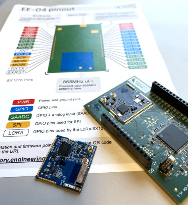
Rummaging through the hardware archive (aka the old boxes with old projects) yielded results - I found both a development board and a module. It even included a pinout diagram:
The gateway setup should look something like this:
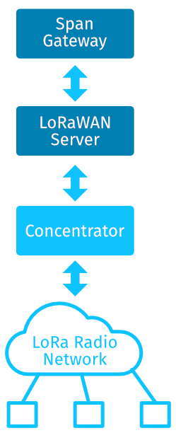
- One or more LoRaWAN devices that runs on the EE-04 board (the one with the header pins above)
- A concentrator that forwards the LoRaWAN traffic via a packet forwarder (in essence a lora-to-udp service)
- A LoRaWAN stack of sorts
- Span gateway which will keep the devices in Span and the LoRaWAN server in sync.
It’s a few moving parts but the concentrator is probably easier to place on the outside since it will be a standard component (possibly even a separate device) and the Span gateway will embed the LoRaWAN server component.
A LoRaWAN Concentrator
In order to communicate with the devices I’ll need a concentrator/gateway for LoRaWAN. After rummaging through even more boxes I found an old IMST ic880a concentrator board and wired it up to a Raspberry Pi. We also had a Kerlink gateway but it’s anything but desktop friendly and the serial port adapter is … somewhere. With a Raspberry Pi I can run both the concentrator and the Span gateway on the same computer.
To be honest it’s been a few years since I set up a Raspberry Pi with a LoRa packet forwarder built from the packet forwarder sources and the libloragw driver talking to a IMST ic880a board. The biggest hurdle was figuring out the correct Raspberry Pi pins to use. Just like five years ago.
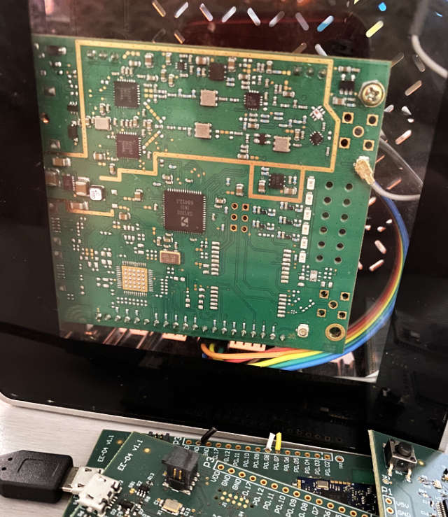
We had a lot of different antennas in the boxes and I think I found a 868MHz antenna (it might be a 915MHz or 433MHz) but as long as the impedance is correct I don’t worry too much about the range. It will mostly talk to devices a few meters away and if the range is horrible I’ll test another.
A bare bones LoRaWAN stack
Next I’ll need a LoRaWAN stack. I could use ChirpStack but it might be a bit overkill for my needs and I’d like to have the server embedded in my gateway code. The old Congress project has been dormant for the last few years but it still compiles just fine. There’s a lot of features in that server that I won’t be needing such as logins, outputs or a REST API (gRPC is a lot easier to work with). After a few hours the server was slimmed down into a much more maneagable version with a gRPC interface and SQLite for storage.
A bare bones gateway
The first step is to get a bare bones gateway up and running. I’ll start by defining a gateway in Span:
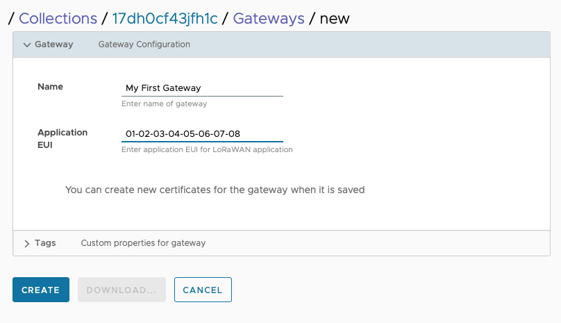
After saving it I can create a client certificate for the gateway:
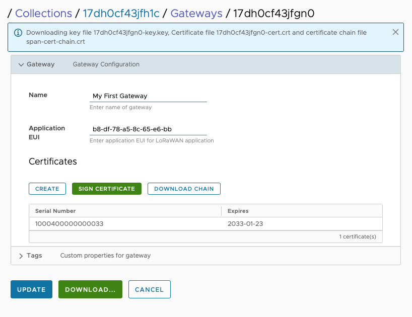
With the certificates I can write a simple gRPC client to connect to Span and verify that it is able to connect and get an updated gateway configuration.
After a few iterations I ended up with a separate library with all of the boilerplate and an interface that looked like this:
type CommandHandler interface {
    UpdateConfig(
        localID string,
        config map[string]string) (string, error)

    RemoveDevice(localID string, deviceID string) error

    UpdateDevice(
        localID string, localDeviceID string,
        config map[string]string) (string, map[string]string, error)

    DownstreamMessage(
        localID, localDeviceID,
        messageID string,
        payload []byte) error

    UpstreamMessage(upstreamCb UpstreamMessageFunc)

    Shutdown()
}
The entire glue code for the LoRaWAN service boiled down to a few hundred lines of code like this:
    func (l *loraHandler) DownstreamMessage(
        localID, localDeviceID,
        messageID string,
        payload []byte) error {
    ctx, done := context.WithTimeout(context.Background(), loraClientTimeout)
    defer done()

    if localID == "" {
        return errors.New("can't send downstream message with no EUI")
    }
    _, err := l.loraClient.SendMessage(ctx, &lospan.DownstreamMessage{
        Eui:     localDeviceID,
        Payload: payload,
        Port:    1,
        Ack:     true,
    })
    if err != nil {
        lg.Warning("Error sending downstream message for device %s: %v", localDeviceID, err)
    }
    return err
}
The firmware
When the time came to write firmware I had several options:
- Use the old EE-0x firmware we wrote 6-7 years ago. It still compiles but it’s haven’t been touched in many moons. It uses Segger RTT for logging which is…. an acquired taste when doing it without an IDE but it should work. The firmware is based on an old version of LoRaWAN (1.0.2) so it might not be very relevant.
- Use the old EE-0x Apache Mynewt firmware we wrote 5-6 years ago. Apache Mynewt was great (it even featured a BSP for the EE0x boards). The Mynewt project has a lot of nice features (the tooling is great and the API is easy to use) but it’s not very active.
- PlatformIO with Zephyr. This is the least painful Zephyr alternative but uses an older version of Zephyr. This is the easiest way to use Zephyr by far but you still have to contend with Zephyr curveballs in the form of device tree configuration, a jungle of configuration options and a clunky API.
- The new nRF Connect SDK. This is great for BLE projects on nRF52 but I’ll be using LoRa and talking with the sx1276 chip. It’s relatively easy to get up and running but it does take quite a bit of time to get all the parts working.
Since I’ll use a board (or combination of board and radio) with zero to none usage it makes little sense to invest a lot of time debugging and troubleshooting so I tried all of the above hoping that one of them would be working.
To make a short story of it: I was wrong. The Apache Mynewt firmware was quite out of date and the new LoRaWAN implementation required a fair bit of troubleshooting and fixing. For obvious reasons the BSP wasn’t kept up to date so I turned to Zephyr and PlatformIO. After a day’s work I was able to figure out the proper device tree configuration (I did have to look into how Apache Mynewt used the SX1276 chip to figure everything out).
After much head scrathing (and -banging) it worked:
*** Booting Zephyr OS build zephyr-v20701  ***
[00:00:00.468,566] <inf> sx127x: SX127x version 0x12 found
[00:00:00.559,295] <inf> lora_demo_device: Joining network over OTAA
[00:00:08.397,460] <inf> lorawan: Joined network! DevAddr: 00d18237
[00:00:08.398,681] <inf> lora_demo_device: New Datarate: DR_0, Max Payload 51
[00:00:08.398,681] <inf> lorawan: Datarate changed: DR_0
[00:00:08.398,712] <inf> lora_demo_device: Sending data...
[00:00:12.071,380] <inf> lora_demo_device: Downlink: Port 0, Pending 0, RSSI -87dB, SNR 9dBm
[00:00:12.072,631] <inf> lora_demo_device: Data sent!
Unless you sit in the office besides me you won’t have much use for the source code but you might end up with a Zephyr project that uses the SX1276 here’s the device tree configuration from the firmware repo:
/ {
    aliases {
        lora0 = &lora;
    };
};

&spi0 {
    status = "okay";
    sck-pin = < 25 >;
    mosi-pin = < 23 >;
    miso-pin = < 24 >;
    cs-gpios = < &gpio0 22 GPIO_ACTIVE_LOW >;
    lora: sx1276@0 {
        compatible = "semtech,sx1276";
        reg = <0>;
        label = "sx1276";
        reset-gpios = <&gpio0 18 GPIO_ACTIVE_LOW>;
        antenna-enable-gpios = <&gpio0 27 GPIO_ACTIVE_LOW>;
        dio-gpios = <&gpio0 13 GPIO_ACTIVE_HIGH>,
                    <&gpio0 14 GPIO_ACTIVE_HIGH>,
                    <&gpio0 15 GPIO_ACTIVE_HIGH>,
                    <&gpio0 16 GPIO_ACTIVE_HIGH>,
                    <&gpio0 19 GPIO_ACTIVE_HIGH>,
                    <&gpio0 20 GPIO_ACTIVE_HIGH>;
        spi-max-frequency = <800000>;
        power-amplifier-output = "pa-boost";
    };
};
Putting it all together
The concentrator
Now let’s get everything up and running. Start with the concentrator. It’ll need a small shell script for the launch which resets the IC880A board and sets the gateway’s EUI to the mac address of the network card:
You might have to edit the server_address if you plan to run the gateway on a different computer. I’m running it on the same Raspberry Pi so localhost works for me:
#!/bin/bash

# Get first non-loopback network device that is currently connected
GATEWAY_EUI_NIC=$(ip -oneline link show up 2>&1 | grep -v LOOPBACK | sed -E 's/^[0-9]+: ([0-9a-z]+): .*/\1/' | head -1)
if [[ -z $GATEWAY_EUI_NIC ]]; then
    echo "ERROR: No network interface found. Cannot set gateway ID."
    exit 1
fi

# Then get EUI based on the MAC address of that device
GATEWAY_EUI=$(cat /sys/class/net/$GATEWAY_EUI_NIC/address | awk -F\: '{print $1$2$3"FFFE"$4$5$6}')
GATEWAY_EUI=${GATEWAY_EUI^^} # toupper

echo "Gateway EUI is ${GATEWAY_EUI}"

cat>local_conf.json<<EOF
{
    "gateway_conf": {
        "gateway_ID": "${GATEWAY_EUI}",
        "server_address": "localhost",
        "serv_port_up": 1680,
        "serv_port_down": 1680
    }
}
EOF

echo "Reset IC880A board..."

# The reset pin of the IC880A board is hooked up to GPIO pin 25
echo "25"  > /sys/class/gpio/export
echo "out" > /sys/class/gpio/gpio25/direction
echo "1" > /sys/class/gpio/gpio25/value
sleep 5
echo "0" > /sys/class/gpio/gpio25/value
sleep 1
echo "0" > /sys/class/gpio/gpio25/value

echo "Launch packet forwarder"
./lora_pkt_fwd
When you launch it it should log several lines to the console. Once it starts running you should see a log line similar to this:
JSON up: {"stat":{"time":"2023-02-08 13:25:43 GMT","rxnb":0,"rxok":0,"rxfw":0,"ackr":0.0,"dwnb":0,"txnb":0}}
The gateway service
We’ve build a few docker images that you can use to launch the gateway so if you have docker installed all you have to do is to copy the certificate, chain and private key files you created previously into the current directory, rename them to clientcert.crt, chain.crt and private.key above, then run the following command :
docker run -v /home/lora/new-gw:/data -p 1680:1680/udp lab5e/loragw:latest
(the -v parameter maps the current directory to the /data volume and -p exposes the UDP port since the concentrator will connect to it)
When it launches you should see something along these lines:
Unable to find image 'lab5e/loragw:latest' locally
latest: Pulling from lab5e/loragw
c527615e4ffa: Pull complete
bd978ef01539: Pull complete
Digest: sha256:a7d9d6871ce8f1a601ffc3e9d00e3b093aa0b1c3034706af0ad0399690e0ac0b
Status: Downloaded newer image for lab5e/loragw:latest
[Info] Updating gateway config with application EUI: f0-ab-19-29-b7-a7-df-77
The EUI will of course depend on what you used when you created the gateway.
Add a new device in Span, then click on the “Configure” button in the gateway section:
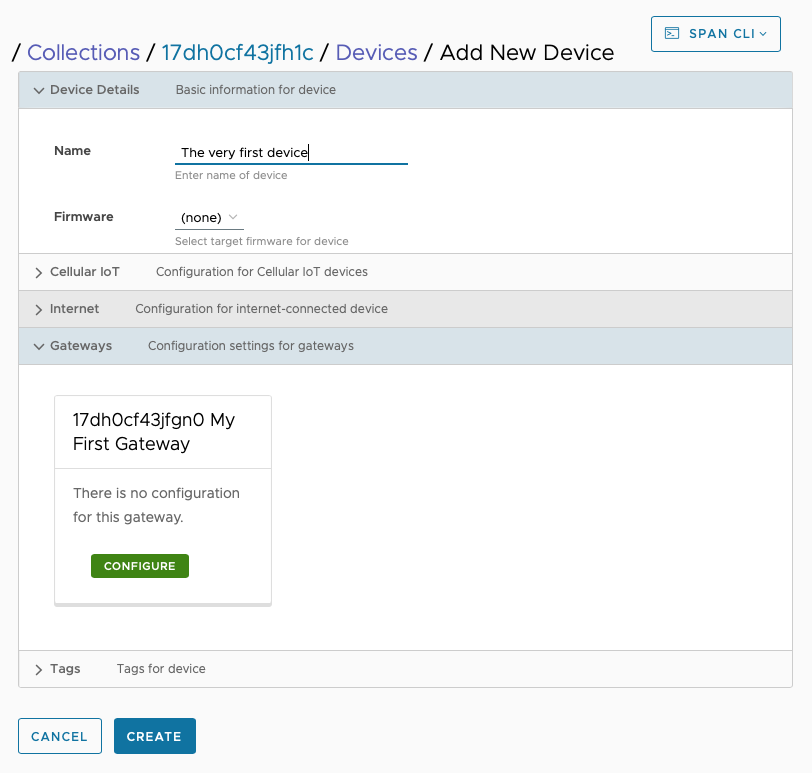 I’m setting the device to OTAA (aka Over The Air Activation) and set the EUI for the device and the application key:
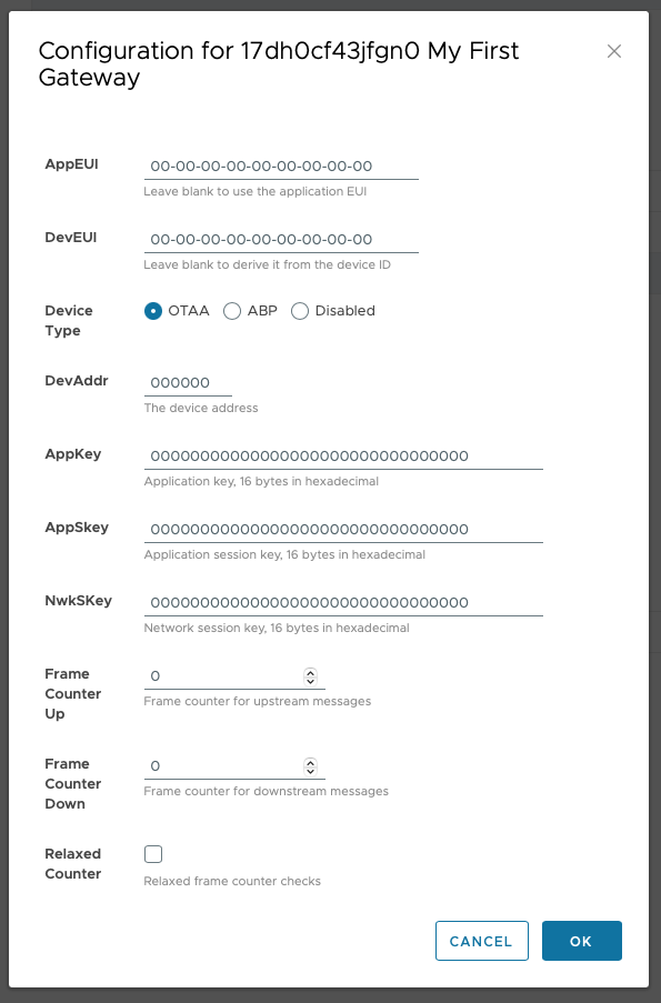
Once you click on the “Create” button in Span you should see a log message on the gateway:
[Info] Created new device aa-bb-cc-dd-11-22-33-44
(obviously there’s no points awarded for the EUI numbering scheme here)
We’re now ready to do the last piece of the puzzle - the LoRa device itself.
The firmware
To configure the device I’ll need the device EUI, the application/join EUI and the application key. Click on the “C Code” button to get a code snippet you can copy and paste into your source code. As mentioned earlier, I used PlatformIO and Zephyr for the firmware so it’s easy to build and upload the firmware:
pio run -t upload
If everything goes well you should see the device connect in the Zephyr logs:
*** Booting Zephyr OS build zephyr-v20600  ***
[00:00:00.458,648] <inf> sx127x: SX127x version 0x12 found
[00:00:00.549,865] <inf> lora_demo_device: Joining network over OTAA
[00:00:08.425,994] <inf> lorawan: Joined network! DevAddr: 01d19486
[00:00:08.426,055] <inf> lora_demo_device: New Datarate: DR_0, Max Payload 51
[00:00:08.426,055] <inf> lorawan: Datarate changed: DR_0
[00:00:08.426,086] <inf> lora_demo_device: Join successful
The sample firmware is set up to send data once a minute so after a while it should start sending a simple “hello world” to Span:
Upstream messages
The Zephyr implementation is quite strict on the duty cycle (as it should be) so the first attempts might not succeed but eventually you should receive a message in Span with the text “helloworld”.
[00:01:08.426,177] <err> lorawan: LoRaWAN Send failed: Duty-cycle restricted
[00:01:08.426,208] <err> lora_demo_device: lorawan_send failed: -111. Continuing
[00:02:08.426,269] <inf> lora_demo_device: Sending data...
[00:02:08.426,330] <err> lorawan: LoRaWAN Send failed: Duty-cycle restricted
[00:02:08.426,361] <err> lora_demo_device: lorawan_send failed: -111. Continuing
[00:03:08.426,422] <inf> lora_demo_device: Sending data...
[00:03:12.099,487] <inf> lora_demo_device: Downlink: Port 0, Pending 0, RSSI -76dB, SNR 8dBm
[00:03:12.099,548] <inf> lora_demo_device: Data sent!
At the same time the gateway should log the message:
[Info] Sending upstream message from aa-bb-cc-dd-11-22-33-44 to Span (10 bytes)
…and the Inbox page in Span will now show a message from the device:

Downstream messages
Go to the Outbox page, select the device and create a downstream message. Click on “Send message” to send it:
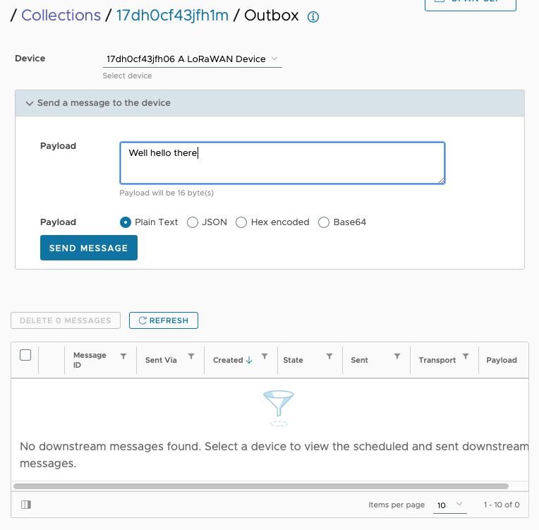
The message status should be “Pending” until the device sends a message upstream:
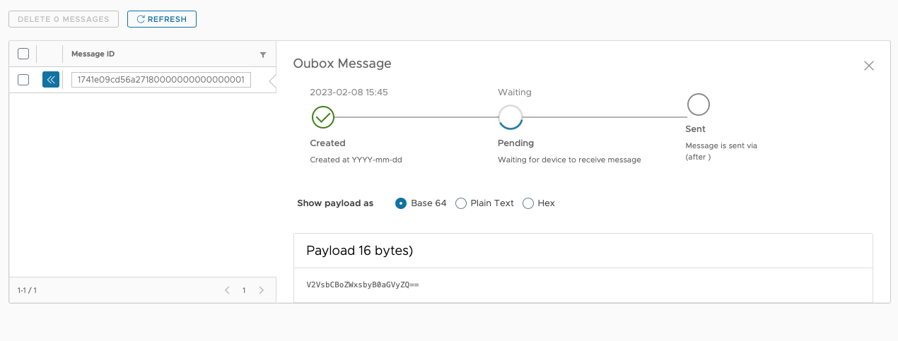
When the device sends the next message the gateway should receive the new downstream message:
[Info] Sending confirmed message to aa-bb-cc-dd-11-22-33-44 (16 bytes) on port 1
The device might not receive the message immediately but after the next receive window it should arrive on the device. Patience is a virtue!
[00:12:19.446,929] <inf> lora_demo_device: Sending data...
[00:12:23.612,152] <inf> lora_demo_device: Downlink: Port 1, Pending 0, RSSI -74dB, SNR 8dBm
[00:12:23.612,182] <inf> lora_demo_device: Received payload:
                                           57 65 6c 6c 20 68 65 6c  6c 6f 20 74 68 65 72 65 |Well hel lo there
[00:12:23.612,213] <inf> lora_demo_device: Data sent!
That’s it!
P.S
The LoRa gateway in the docker image isn’t production ready but it’s relatively trivial to implement a gateway wrapper for ChirpStack, The Things Network or another LoRaWAN service.
