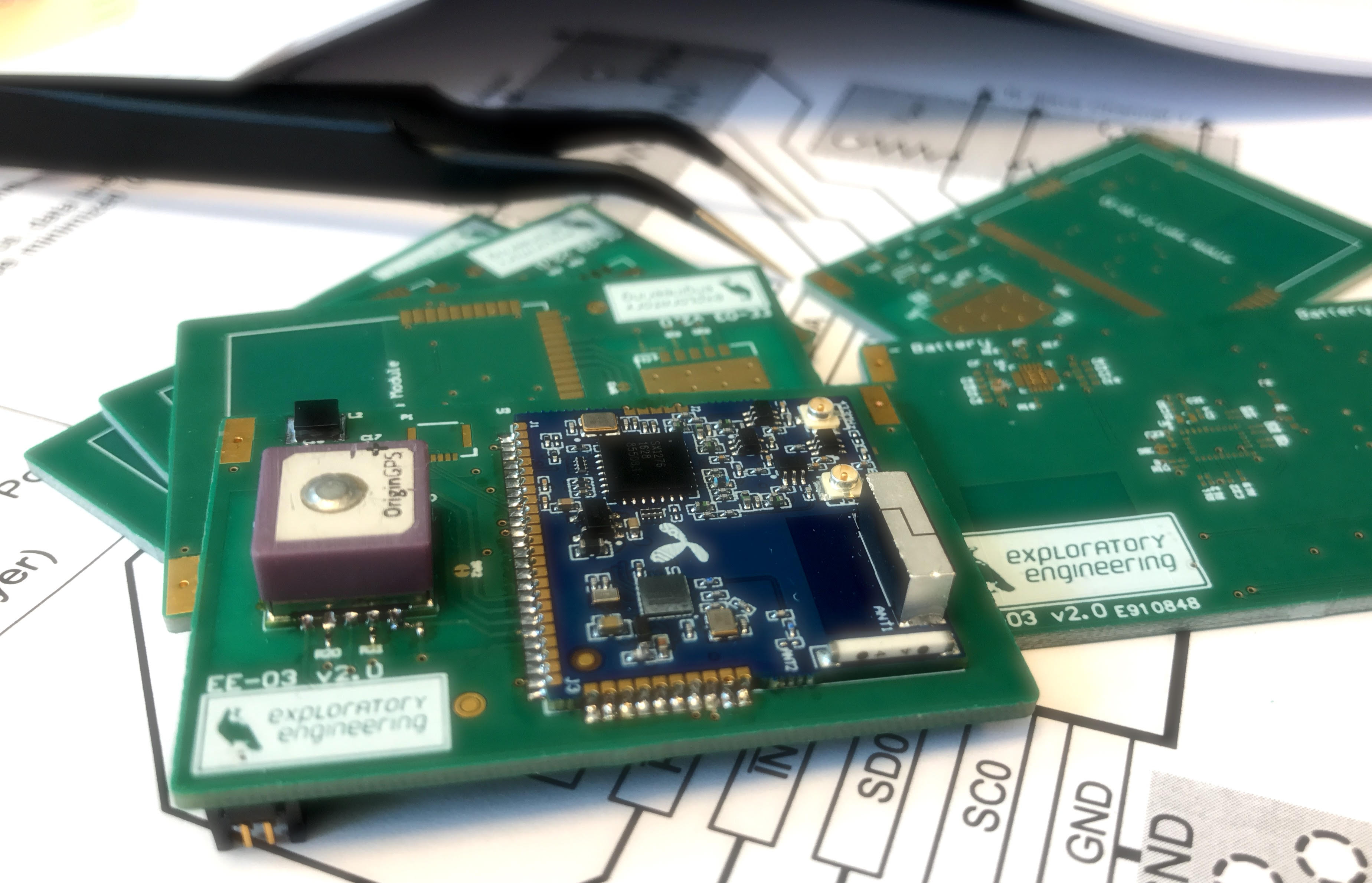
Ok, so we changed out the IMU on our EE03 Lora/GPS/IMU-tracking device.
Swapping out one I2C device with another I2C device shouldn’t cause any side effects, right ?
We previously used the LSM9DS1 in our tracker. After playing around with the BNO055, this seemed to have superior performance characteristics, sporting an onboard MCU that could do sensor fusion, providing a 100Hz Euler angle feed.
Both are 3.3V devices. Both are I2C devices. Updating the design to incorporate the BNO055 instead of the LSM9DS1 seemed like a good idea.
Similar to the LSM9DS1, the BNO055 has two voltage lines. The BNO055 has one for the sensors (VDD) and one for the onboard 32 bit cortext M0+ microcontroller (VDDIO). A LoRa device has to be power efficient, so we use a quad channel load switch (TPS22994) in order to manage power to on board slave devices, like the GPS and the IMU. We proceeded to implement the correct power up sequence for the BNO’s power lines.
This did not go well - at all.
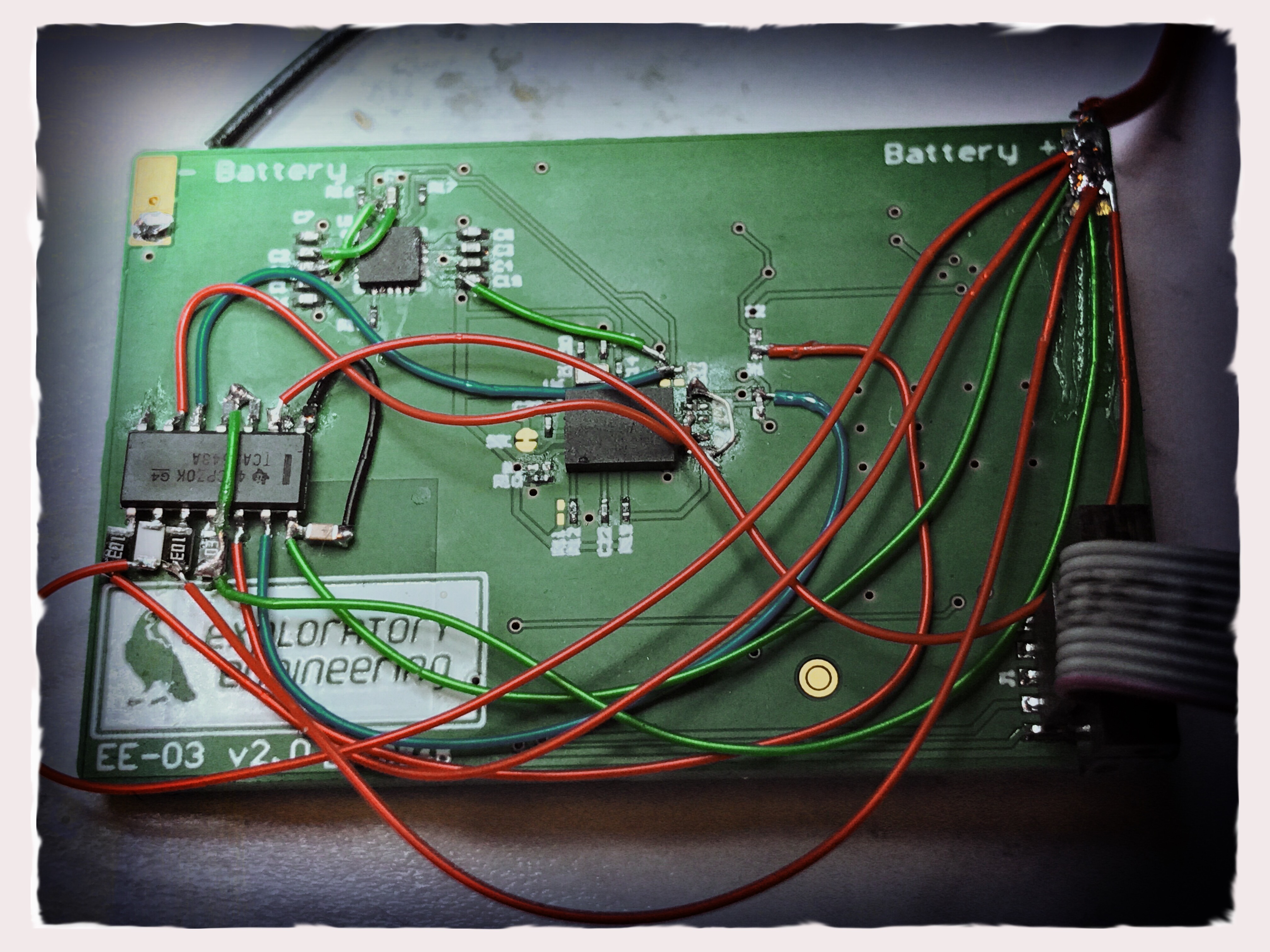
The I2C bus was well and truly dead. It turned out that we couldn’t control the power lines (via I2C) to the BNO055 - unless the BNO055 already was powered on (bodge wires FTW).
It turns out that a BNO055 without power to the VDDIO (for the microcontroller) acts as a current sink via the I2C lines, if these are pulled up to another voltage source that the BNO055’s VDDIO. It will then pull the SDA/SCL signals down and cripple the bus. You can actually measure a voltage of approx 0,5V at VDDIO that is leached from the I2C bus.
The solution was to use an I2C bus switch. We selected the TCA9543A and borged that into our prototype board. This is a device that has three I2C interfaces. On one side it is connected to the master MCU. On the other you can attach one or two slave I2C buses. This is handy if you are attempting to use I2C devices with different voltage requirements on the same bus or have address collisions on the bus.
All you have to do is select the correct I2C channel on the TCA9543A and then use your existing I2C firmware to communicate with your devices. Right… ?
Wrong.
It turned out that the master bus no longer locked up, which was a good thing. The bad thing was that we couldn’t detect I2C clock or data on any of the two slave channels. Had we mounted the chip the wrong way ? Nope. We were able to write data and read data back from the chip’s only control register. The chip clearly worked. Still it didn’t. After checking and re-checking all connections to the chip, we decided to take another look at the data sheet - and our firmware…

In our tests, we had sent one byte to the TCA9543 control register in order to switch on one or both channels. We had then signalled a stop condition on the bus. Expecting the TCA to the be a transparent device.
Wrong.
Turns out that you need to signal a start condition, select channel, communicate with the slave device and then, and only then, signal a stop condition on the bus.
We now have a working device. Yay !
Further reading
- BNO055 - Intelligent 9-axis absolute orientation sensor.
- TPS22994 - I²C Controllable Load Switch.
- TCA9543A - Low Voltage 2-Channel I 2C Bus Switch.
- LSM9DS1 - iNEMO inertial module.
Resources
Giphy for gifs (https://media.giphy.com/media/jzQXsabuFUUX6/giphy.gif)