It’s business as usual in the Exploratory Engineering labs. We’re still in IoT mode and NB-Iot is the order of the day. We’re currently playing with uBlox NB-Iot modules, while eagerly awaiting the upcoming nRF91 low power cellular IoT chip from Nordic Semiconductor.
That doesn’t mean that we can’t indulge in side projects from time to time. Especially if the end result can save us time and money down the road. Sometimes we get a bit carried away, though. The current tangent some of us are on, involves the construction of a pick and place machine. These are necessary for populating printed circuit boards in larger batches.
When we are making just a handful of prototypes, we’re populating these manually, using pincers and a stereo microscope. Needless to say - this process does not scale well. Larger batches require outsourcing of the process to a third party, where we have to wait for available time slots.
It would be great if we could run these batches in-house, but commercial machines are a bit expensive for our tastes and purchasing one also would commit us to investing in months of training on horrible proprietary windows software :)
A PnP machine is just a precision XYZ gantry. A Big one. Containing up/down cameras with object detection capability, vacuum system, servo controllers with onboard PID tuning, custom controller boards and multiple component feeders.
Building one shouldn’t be much more complicated than building a bog standard giant sized 3D printer (with micron precision and lightning speed…). The open source 3D printing ecosystem is densely populated. Building a printer from scratch is no more complex than an exercise in Lego construction. The Open PnP ecosystem is somewhat more sparsely populated. Building a PnP machine therefore involves a certain amount of thinking, designing and creating functional components from scratch.
Doing a project, any project, is relatively straight forward. You start doing the first thing that you can do, then you move on to the next thing that brings you a verifiable step closer to a finished product. When you run out of things to do, the project is a success. If you run out of time or manager / customer patience, you have failed.
This process is often slightly reminiscent of providing your manager with a random number, indicating estimated effort for completion, then starting the project clock, then diving into a fractal rabbit hole with recursive branches, located in earthquake territory, near an active volcano. The finished product already lies in wait, hidden near the exit of the maze in spacetime. Your only job is to locate it before your local, subjective time runs out.
I’m not going to describe the entire machine in this post, but instead focus on an interesting side branch. There will me more blog posts on this topic - even if we fail spectacularly. Promise :)
As mentioned earlier a Pick and Place machine is a tool for automated assembly of printed circuit boards, using surface mount components. Components come in strips or reels, containing potentially thousands of individual components. Controller software reads in the design and instructs the machine to pick components and the place them on a PCB.
Each component type is held in a dedicated component feeder that the PnP communicates with when it needs to place the next component.
This easily qualfies as a rabbit hole in it’s own right. (Fractal - remember ?)
Our first instinct was to look for open source component feeders. We found one that looked like it could actually work. The design was based around laser cut and 3D printed parts, along with a humongous set of spacers in not-too-easily-available dimensions. Some of the parts were hard to source. Unless we modified the design, we probably would have had to source hardware fittings from a corner shop in Vietnam. Otherwise, the design seemed quite sound. That was - until we discovered that a critical part in the construction was - wait for it - a piece of string.
We decided to move on, explore a new path and design our own feeder. As usual, we had constraints:
- It had to be cheap. A lot cheaper than commercial feeders.
- The parts used had to be easy to source or easy to manufacture.
- It had to interface smoothly with the PnP machine both mechanically and electrically.
- It had to be as slim as a commercial feeder. (One run may rely on 150+ individual components, with each contained in a separate feader. We also have to be able to physically fit all feeders in the machine simultaneously)
- It had to be fast enough to keep up with the XY movements of the PnP machine.
- It should be able to accomodate component tape strips of different sizes.
- it had to actually work. Reliably.
Several new paths opened up in the rabbit hole. Branching ones.
Physical construction / side panels.
Needless to say, the feeder has to be made of some material that will hold the mechanical and electrical components in place and also allow it to attach/detach easily to/from the frame of the machine. Since it needs to be rather slim, preferably not much more than 14 mm, the material will have to be in the “flat stuff” category. There are several options open to us:
-
3D printed / FDM fabrication ? This is a cheap process, but a time consuming one. It also put’s restrictions on the physical size of the feeder. Designing something that could only be manufactured at a professional 3D printing service wouldn’t make sense. The flexibility of printed parts is another potential issue. Using this process, the side panels would have to be made rather thick, in order to be rigid enough.
-
Laser cut acrylic ? This is a fast process, but materials are more expensive than those being used for FDM 3D printing. Still, rigidity is an issue with thin acrylics. We need a slim feeder, and thick side panels leaves less room for electronics.
-
PCB laminate ? This is expensive in small quantitites, but the cost drops dramatically even in modest quantities. It also translates into less need for wiring, since electronics and wires can be embedded in the side panels. Rigidity is no problem, even for PCBs down to 1mm in thickness. It has to be realized as a two layer board, in order to keep the cost down, but the extra routing effort needed in order to accomplish this is a one time cost of a few hours work. Definetly worth it. By bootstrapping the machine with a small set of manually assembled feeders, the PnP machine could also manufacture more of its own feeders. Which is nice - in a Von Neumann way :)
We decided to go for the last option, but to prototype early iterations of the device using the Delta Wasp in the lab.
The morphology of component strips.
In order to feed something, it is probably a good idea to know something about the stuff you are going to feed. Component tape strips comes in various shapes and sizes. Fortunately these adhere to standards.
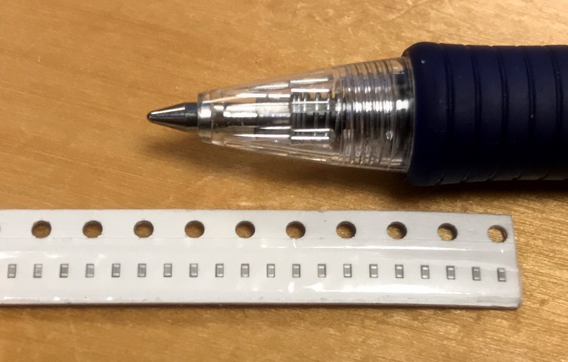
The tape strip in the picture is 8mm wide. It has a series of holes on one side, and holds a set of components on the other side. A component resides in a small pocket under a tape that has to bee peeled off before it is available for picking.
The distance between holes is standardized. The number of components per unit of length, along with the width and depth of pockets can vary, depending on component size, but still within a standardized range.
The design goal for the feeder width was in the 12-24mm range. Using PCB as structural side panels, we can fit more feeders to the machine.
Drive mechanism.
The feeder has to have two separate drive mechanisms. One is responsible for feeding exactly one component from the strip, given a signal from the machine. The other one is responsible for peeling the protective tape off the strip.
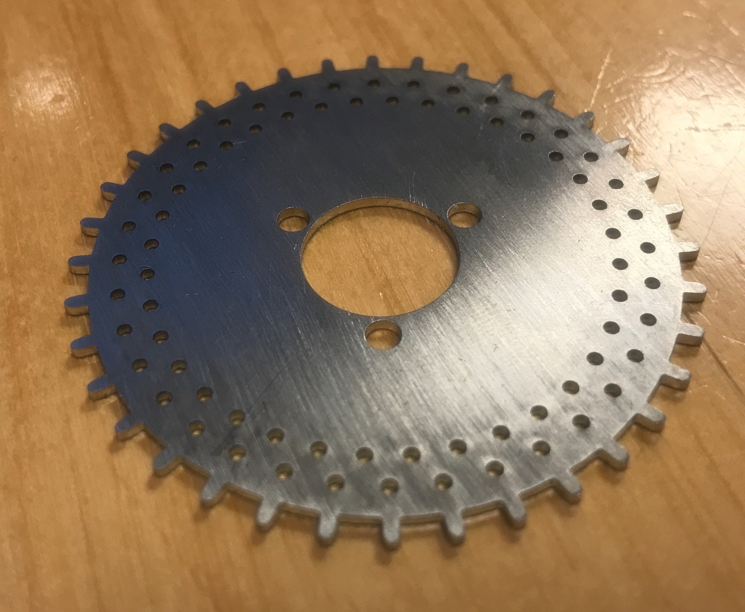
A sprocket gear is the ideal choice for connecting the tape strip to an actuator. We designed a sprocket gear based on measurements taken from a commercial feeder. This could be cheaply manufactured in 2D, using a laser cutter.
A bevel gear could easily be fitted on top of this and act as a power transmission between a motor and the sprocket. Yay.
Bevel gears turned out to be hard to source. Especially in the intended price range. We concluded that we should design our own bevel gears in Fusion 360. Gears that could be 3D printed cheaply. This particular tunnel turned out to open up in a new rabbit hole. We love side quests, so why not learn how to design bevel gears in Fusion ? How hard can it be ?
It turned out to be mind-numbingly hard. I went through the following process:
- Study bevel gear mechanics.
- Attempt design of parametric bevel gear pairs.
- Fail.
- Despair.
- Google intensely for “bevel gear design tutorial” videos.
- Re-attempt design of parametric gears.
- Succeed :)
I hit the jackpot in Step 5. Yay! The level of detail necessary to understand the design is beyond the scope of this post, but if you are a gearhead, I can highly recommend the following tutorial on YouTube:
The picture below shows a rendering of early design of sprocket and bevel gear pair along with a motor.
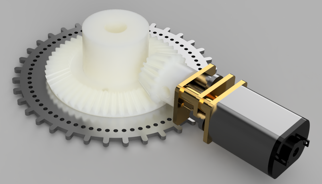
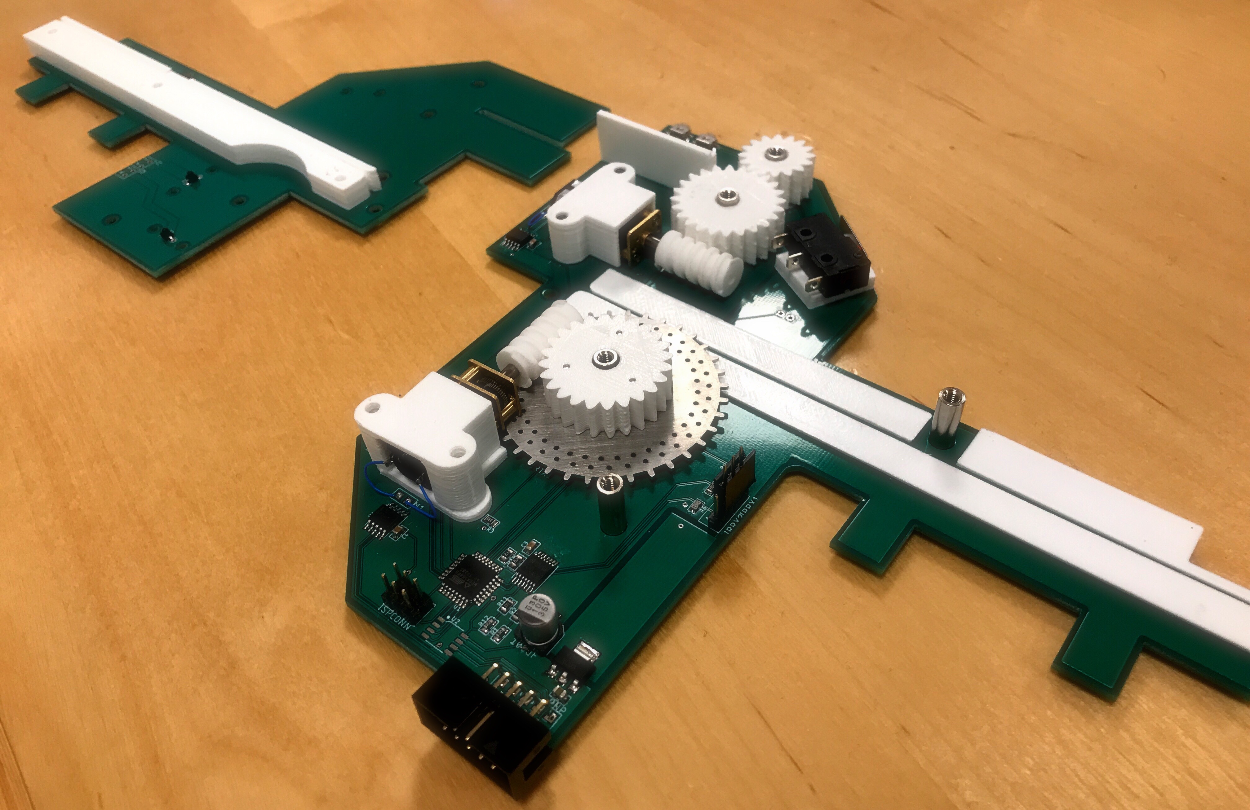
Below is the first physical prototype. The 3D printed bevel gear is attached with 3 M2 screws from the underside of the laser cut steel sprocket gear. Embedded ball bearings ensures smooth travel.
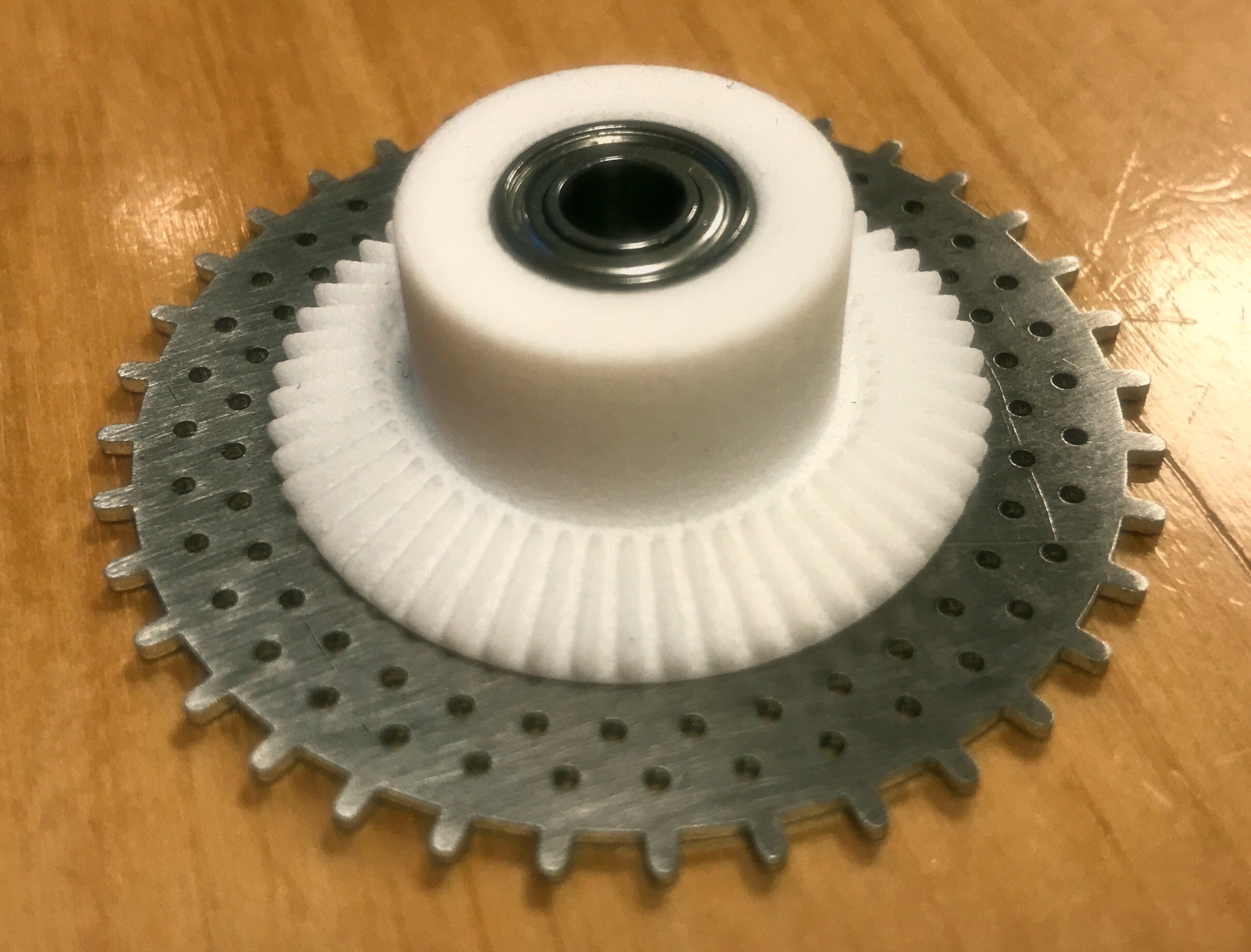
It sure looks good, but someone got so blinded by the sheer coolness of doing parametrized bevel gear design that he/she (me…) forgot to do the math on this thing. It turned out that the torque at outer rim was rather insufficient. We had lot’s of speed though. Too much, in fact. It would perform really well as a miniature model dragster car drive. In a component feeder - not so much. Back to the drawing board.
The solution turned out to be bolting a standard spur / worm drive pair to the sprocket. This gave us a manageable reduction ratio, non-insane range of speed and also enough torque to drive the component strip through the feeder.
Actuators!
I have already revealed some motor details, but deciding on which motors / actuators to use for this wasn’t exactly easy. This choice was just another crossroads in the maze of tunnels in our rabbit hole. The following branches opened up:
-
Pneumatic power ? This would require special (and probably expensive) couplings and valves, and was therefore not an option.
-
Solenoid based linear actuators? This kind could theoretically be used, but they have very limited torque in small form factors. The stroke length is short and torque is not linear along the travel path. Coupling this kind of motion would probably involve some form of watch-like escapement mechanism for 2.5 degree steps. This translates to more custom metal parts. We did not explore this path.
-
Stepper motors? We know stepper motors. We like stepper motors. The bad thing is that our beloved Nema 17s are way to clunky to be used in this applications. As we go down the ladder, it turns out that the same goes for Nema 14 and Nema 8. Fortunately, it turns out that you can get really, really tiny stepper motors that would fit inside the feeder frame. Unfortunately, the step angle on these types of motors are closer to 18 degrees (20 steps per revolution), than the 1.8 degrees (200 steps per revolution) we are familiar with in the Nema range. This is way too coarse without using a gearbox. Geared stepper motors also does not come in form factors that would fit in our assembly. With heavy gearing and a theoretical max stepping speed defined by voltage / inductance / series resistance, stepper motors turned out to be a no-go.
-
Servos? Microservos could probably work. Why didn’t we think of that ?
-
DC motors? These are much higher RPM motors then stepper motors and also requires a gearbox for applications such as this. Fortunately you can source small, cheap, geared DC motors without breaking a sweat. These are the classic N20 motors. They are tiny, have loads of torque (for their size) and will fit within our enclosure just fine. You can get them in a wide variety of reduction ratios as well. Perfect for our use. You can also get them with hall encoders on the shaft. Yay !
Which leads us to the problem of:
Encoders
A stepper motor will perform a single step when you tell it to. Similarly a DC motor will spin the rotor as long as you apply power. In theory. In practice, you will experience lost steps with steppers, and you definetly can not rely on timing when it comes to DC motors. Physics tend to get in way of good intentions :). In appliations like this, we need closed loop control. This translates to using encoders that we can use to accurately determine if the desired move actually has been performed.
You probably noticed the two concentric rings of tiny holes in the sprocket gear. These are encoder holes for an optical encoder. Each hole is spaced 5 degrees apart and the rings are offset by 2.5 degrees. By placing infrared emitters on one side and phototransistors for the same wavelength on the other side, we will now detect exactly one pulse when one of the tiniest components we’re aiming for are fed from the feeder. Larger components will trigger more pulses, but it will be an even number. No ugly fractions :)
Initial selection of microcontroller was done using the usual procurement process: “Cheap!. Familiar! Lot’s of GPIO!. Comparator! Add to basket! Wait for DHL! DoH!”. We ended up using an AtMega168. Turns out it has only one comparator, which would have been just fine in the case of one circle of encoder holes. It turned out that having that many encoder holes in one circle made the IR openings so small that we would get light leaks. It would have been difficult to assemble / align manually. No worries, though. We bolted on another cheap component to solve the problem. Which leads us to the electronics part:
Electronics
This schematic / layout is subject to change without notice (Clone at your own risk). After integration testing we’ll drop schematics, layout, bill of materials and source code on GitHub.
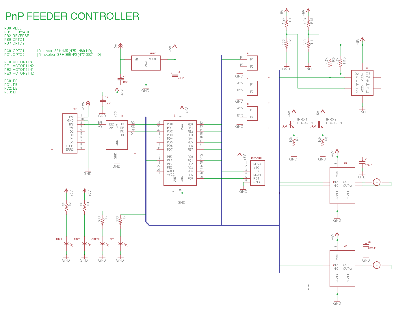
Since I like to keep things simple when prototyping, I chose a LM1117-5 regulator to drop from PnP bus voltage (tentatively 12V) to 5V. Drop “too much” voltage or draw “too much” current and it gets hot. Really hot. I’m not concerned though. If we end up with an egg frying device, we’ll swap it out with a nice cool running buck converter after we have verified that everything else works as intended (buck/boost regulators tend to require more support components than linear regulators)
The feeder bus will most likely not carry 10 signals, but we have still chosen a 10 pin IDC connector for the feeder, since it adds a contact point that is mechanically stable. This connector has power, ground and RS485 signals (termination is done on the bus)
As we can see, an AVR microcontroller handles all the necessary processing. We have two LEDs available, that can be used to signal state visually. Two buttons can be used to manually forward / reverse tape. The peeler mechanism is activated by an open limit switch.
A LM339 is hooked up as a two channel zero crossing comparator. This takes input from two phototransistors and generates nice logic level signals on PC01 or PC1 when one of the encoder holes aligns with one of the two 860nm emitters.
Motors are controlled via two LB1930MC motor controllers. These are H-bridge devices with enough current rating to handle our N20 motors. Two logic level signals are used to indicate fwd, rev, brake or stop to the controller.
Chain of prototypes
Prototyping is what got us here. Prototypes are not necessarily pretty or functional, beyond validating a certain aspect of a design. Once validated, the design can evolve further with a higher degree of confidence.
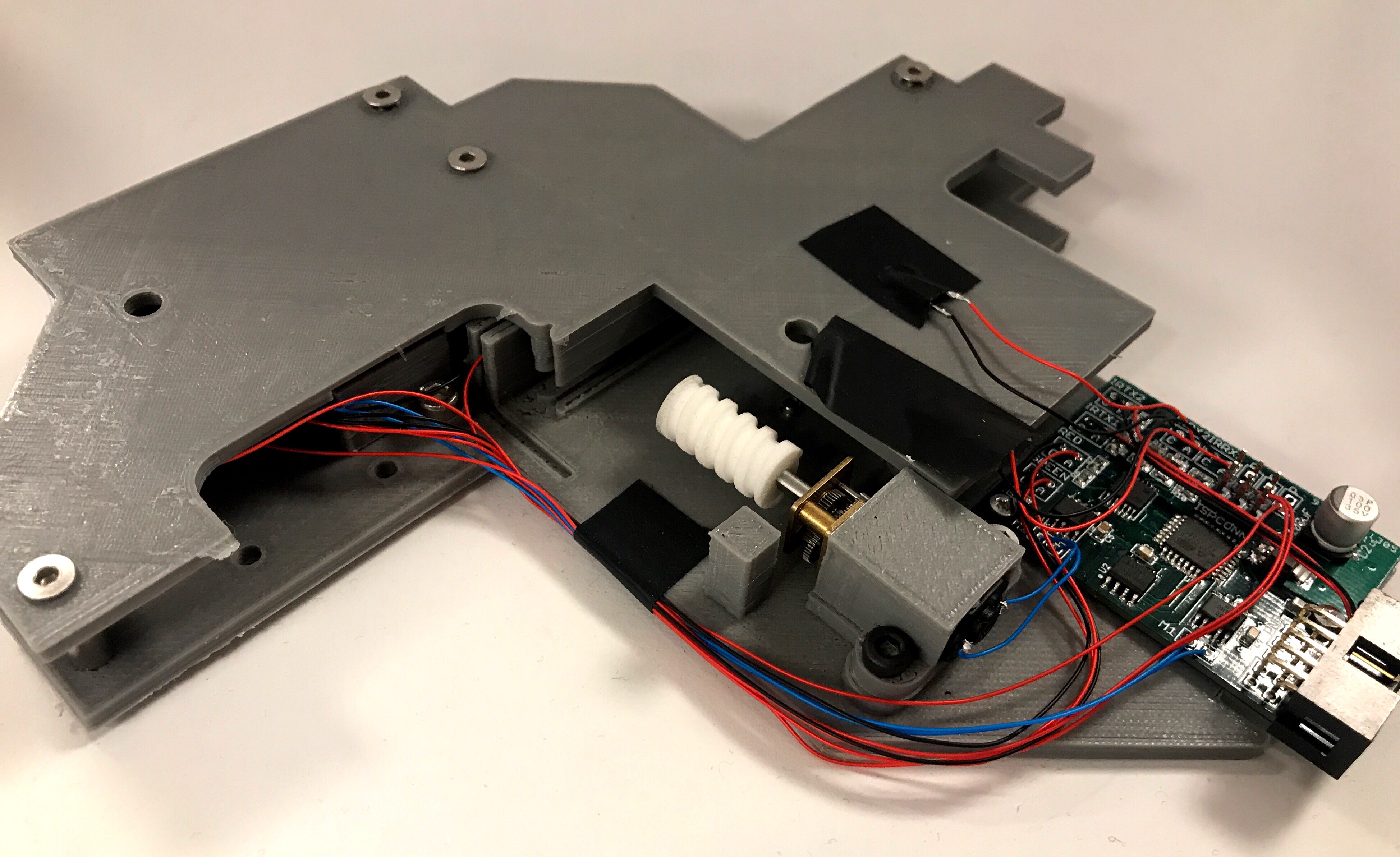
Below is a picture of the first version. This has 3D printed side plates and a separate controller PCB. Since everything that it controls is in another physical location, there are wires - lots of wires. Assembly was a bitch. No thought about physical interface to machine yet. This version was not able to trigger on signals from the phototransistors, so we used this version to test the external comparator - resulting in even more wires, tape and glue. We made it work and modified the Eagle schematic according to what we had learnt.
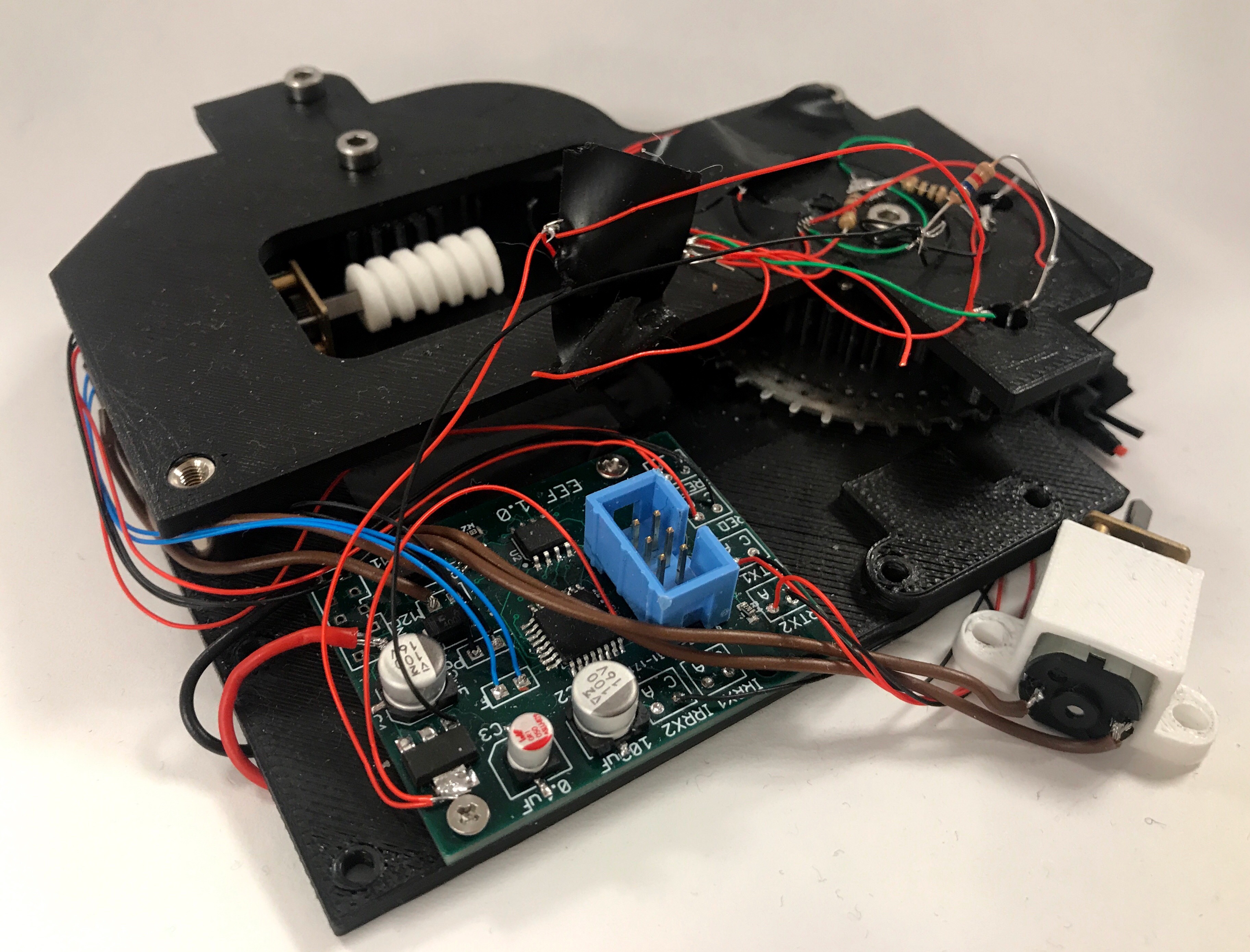
This was our second version. This has a functional comparator and we have also given more thought to the electrical and physical interface to the PnP machine. The infrared emitters and phototransistors are still through hole types. These are replaced by SMD variants in the PCB version.
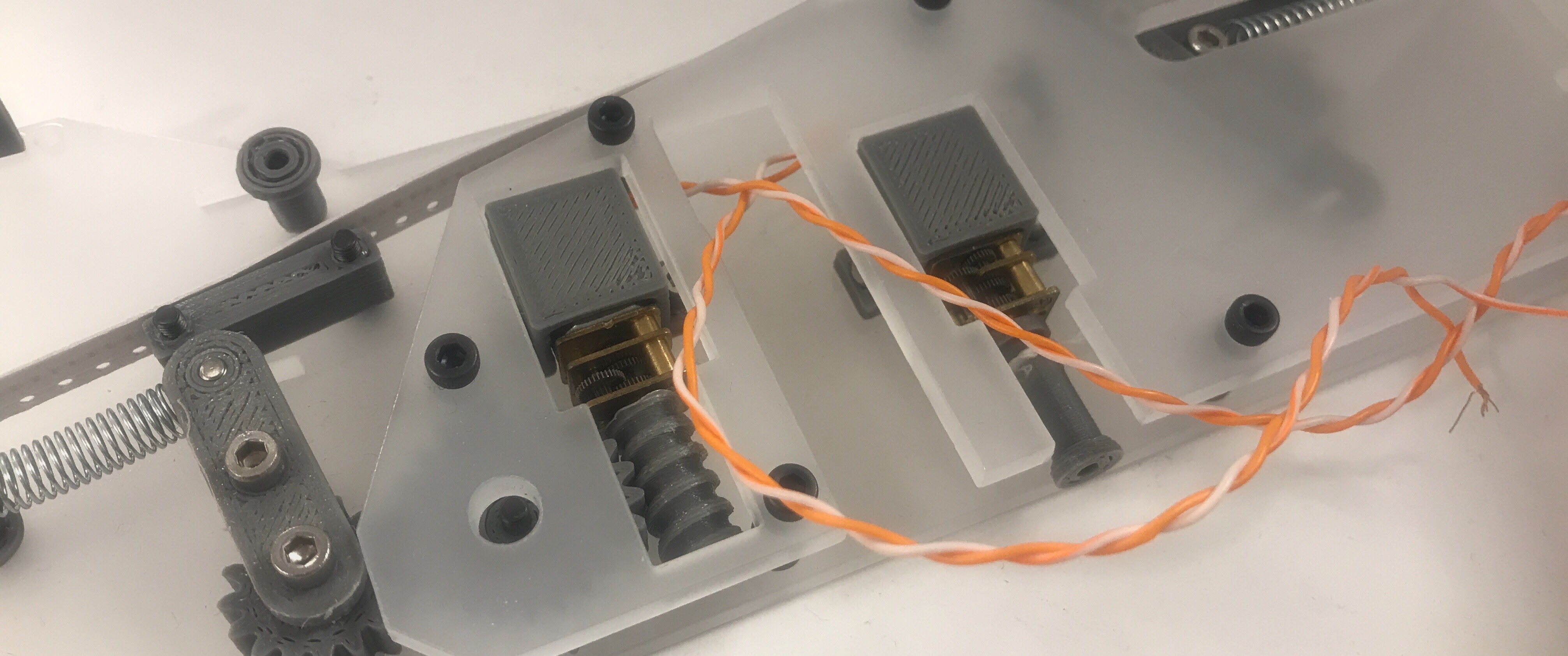
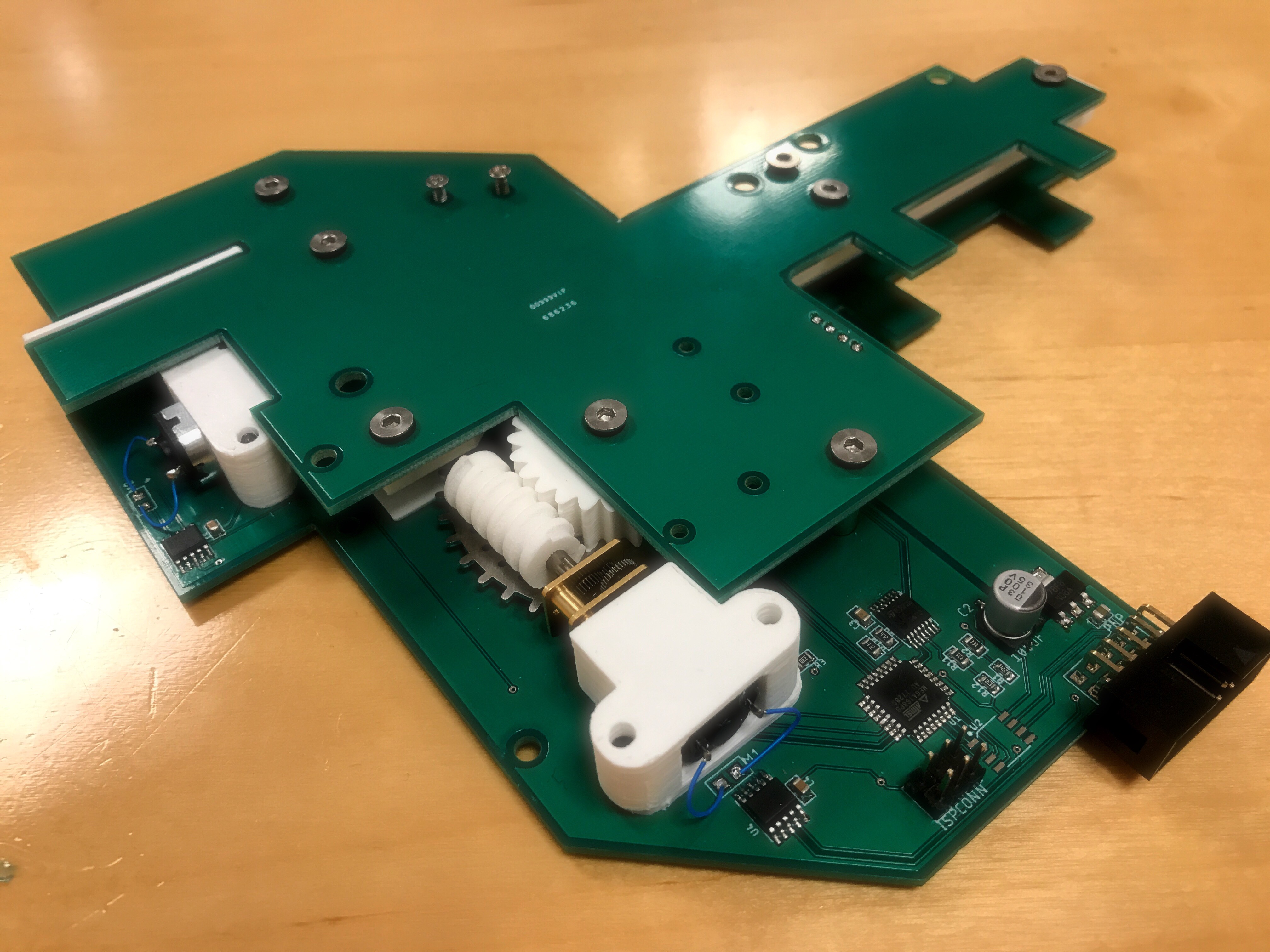
 This is the third (current) iteration of the feeder prototype. All electronics are now embedded on the structural parts. The infrared transmitters and phototransistors are surface mount. A board interconnect supplies power to the transitters on the B board.
A 3D printed component tape guide is attached with 3 M3 screws. This part can be swapped out in order to accomodate other component tape sizes. up to 12mm width. Bigger tape sizes could be accomodated by swapping out the internal 13mm spacers with longer ones.
This is the third (current) iteration of the feeder prototype. All electronics are now embedded on the structural parts. The infrared transmitters and phototransistors are surface mount. A board interconnect supplies power to the transitters on the B board.
A 3D printed component tape guide is attached with 3 M3 screws. This part can be swapped out in order to accomodate other component tape sizes. up to 12mm width. Bigger tape sizes could be accomodated by swapping out the internal 13mm spacers with longer ones.
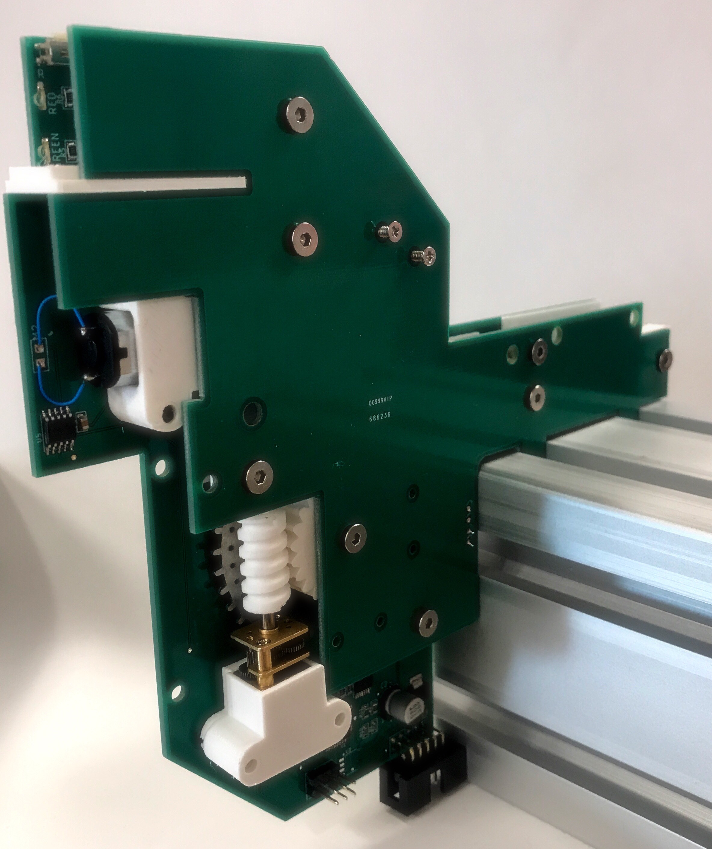
Feeder attached to a piece of 80x80mm aluminum extrusion (same type that is used in the PnP machine frame.)
I expect that we will go through one more iteration before the design is stable. I had introduced a bug in the layout of the B - board, since the board interconnect was offset by 2,54mm (The transfer from a Fusion 360 sketch, via DXF to Eagle ULP DXF import worked, but that’s about it. Manual adjustments had to be made in Eagle. I briefly considered adding our logo to the gerber files, but since this would have involved converting bitmaps in Microsoft Paint - it was abandoned.
I also have to verify that the RS485 transciever works as expected. The firmware is still sketchy, beyond verifying that motors, switches, leds and encoders work. The rest is just code.
We’re aiming for a precision that enables the feeder to handle 0201 components. These components are 0.6 x 0.3mm in size and have to be fed to an exact spot in the pickup area on the feeder. We’re still not quite there yet, but we’re getting closer.
(Manual operation of the primary feeder mechanism, without the peeler)Preliminary BOM
At this point, the BoM is indicative and is subject to change.
Electronics.
- U1. AtMega168 microcontroller.
- U2. ISL8487 RS-485 Transciever.
- U3. LM339 Comparator.
- U4, U5. LB1930MC Bidirectional Motor Driver.
- LM1117-5 Linear Regulator.
- 2X VEMD20x0X01 Phototransistor.
- 2X SFH 4451 Infrared Emitter.
- Generic red LED. Generic green LED.
- 2 x 33 ohm resistors.
- 4 x 330 ohm resistors.
- 2 x 1.2kohm resistors.
- 0.1uF capacitor.
- 10uF/16V capacitor.
- 100uF/10V electrolytic capacitor.
- 2 x 0.22uF capacitor.
- 2 x N20 motors. 200:1 Reduction ratio.
- 1 x genereic leaf limit switch.
- 2 x generic switches.
Custom fabricated parts:
- 1 x 1,6mm PCB left side
- 1 x 1,6mm PCB left side
- 3 x 3D printed spur gears
- 1 x steel sprocket gear
- 2 x 3D printed worm gear
- left and right tape guides (swap these out to accomodate different tape sizes)
Mechanical parts:
- 5 x 13mm M3 stand offs
- 2 x ball bearings. ID 5mm, OD 10mm, H: 5mm
- 3 x M2 8mm screws.
- 4 x M2 6mm screws.
- 13 x 6mm M3 screws.
(All screws are of countersunk type)