
Beyond Cool
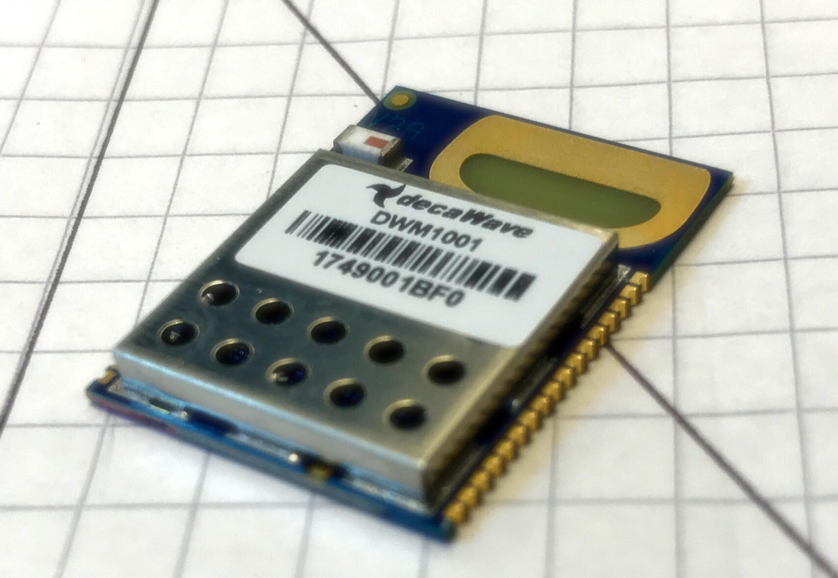
Every once in a while, a piece of tech comes along, that is so cool that it blows your socks off. Enter the DecaWave DWM1001 module.
This little 19 by 26 mm beauty contains a nRF52 microcontroller and a DWM1000 ultra-wideband transciever. Stick 3 or more of them on the walls around the workplace and you have an indoor version of GPS. Instead of GPS satelites, you will have “anchors”. Instead of GPS receivers, you will have “tags”. Identical hardware. Different configuration.
Anchors are configured with location information, in the form of a x,y,z coordinate. Anchors are stationary and together they form a mesh network.
Tags are mobile and are used to track the physical location of whatever they are integrated in - with centimeter precision (DecaWave promises maximum 10cm error). A tag recevies location data and distance to anchors within range. An onboard location engine calculates the x,y,z position of the tag.
You can choose to use the default location engine or you can roll your own. This is relatively straight forward if everything is on the same plane. Slightly less so in R3 space. Google “trilateration algorithm” or “multilateration algorithm” to get started. The IEEEXplore archive alone, has 400+ papers on the subject.
If using the built in location engine, keep in mind that the units used for anchor coordinates and distance estimates are millimeters.
The update frequency is a functiontion of the number of tags in the network. Using only one tag results in 150 Hz updates. Using 750 tags, you get 0.2Hz updates. Deploy up 9000 tags in a given anchor cluster and the update frequency drops to 0.0167Hz, which is still more than reasonable for many applications.
1. Unboxing and test setup
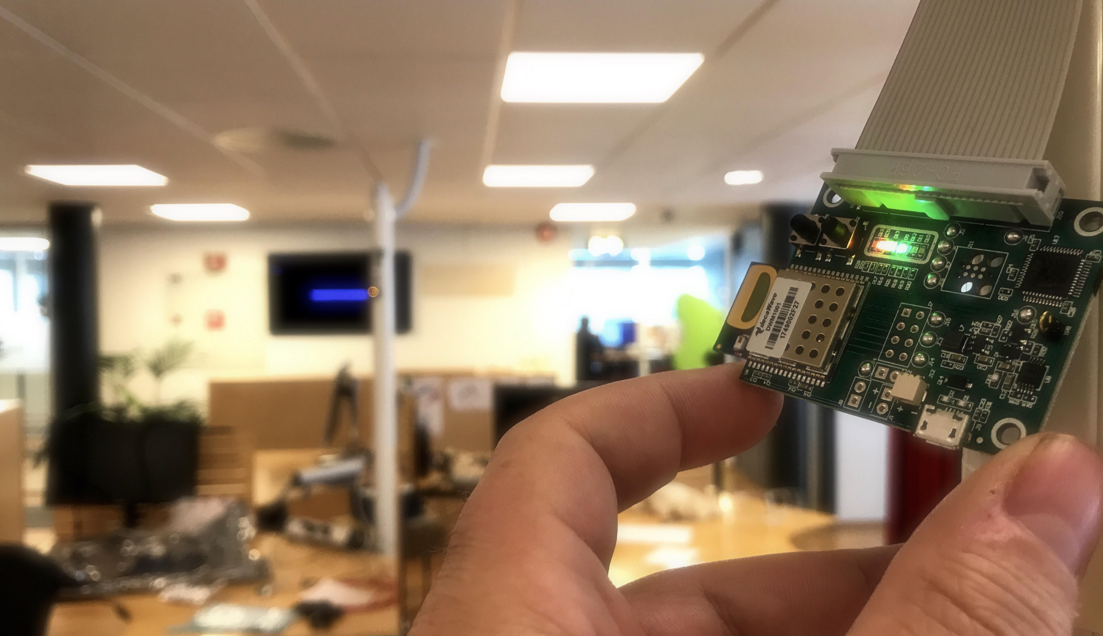
We initially ordered four DWM1001-DEV deveopment kits from DigiKey along with 10 DWM1001 modules. Each kit contains a DWM1001 development board, two cables and an information card describing the board. The onboard DWM1001 module can be controlled by external devices via SPI or UART. If you are feeling brave, it is also possible to add custom code to the onboard nRF52 (eliminating the need for an external controller), as long as you link in the DecaWave libraries (The module is programmable via J-Link).
The SPI/UART interface is only necessary when programming / configuring the anchors, since the configuration is stored in flash.
In order to make life easier for ourselves while testing these devices, we decided to hook each anchor and tag up to a Raspberry Pi Zero W. This is not what you would do in a production environment, but being able to open a remote shell via ssh is never wrong, especially when attempting to get to grips with something new and distributed :)
We ordered a handful of “Seeedstudio Raspberry Pi Zero W barebones kit”, along with some 2.54mm 26 pos connection headers and cable assemblies from DigiKey.
We then deployed three raspberry / anchor pairs in the office and measured the distance between them. Defining one anchor as the origin, we then calculated the position of the other two anchors.
2. Find your devices on the network
The raspberries were configured with Raspbian Stretch Lite. Since these were going to run headless, each SD card was prepared with an empty “ssh” file (thereby enabling SSH on first boot). Similarly, Wi-Fi was enabled by creating a preconfigured “wpa_supplicant.conf” in boot folder.
I then proceeded to scan for open SSH ports on the network by running nmap
I guess that this tool may be considered somewhat “impolite” to use in most organizations. Don’t be surprised if alarm bells go off, or if you are being paid a visit by angry security people. In a sufficiently paranoid organization portscans may be considered a fireable offense.
Anyway, Before powering on any of the raspberries, I executed the following command:
sudo nmap -sS -p 22 10.0.0.0/24
and got a list of ssh-able devices on the network. I then proceeded to power on one raspberry at a time and running nmap afterwards. After I had the IP addresses, I logged in to each one, changed the root password and used scp to transfer the decawave example code to each device.
3. Configure and build
Decawave provides a tarball with example code and documentation. It’s availble from their web site. The file extension is .tar, but it is in reality a 7z file (My mac handled this as smoothly as it would a zip bomb). Rename the file and extract it using 7zip.
In order to define anchor positions, you will have to add the following few lines of code to DWM1001_HOST_API/examples/ex1_TWR_2Hosts/anchor/anchor_cfg.c:
dwm_pos_t pos;
pos.x = 0;
pos.y = 0;
pos.z = 165;
dwm_pos_set(&pos);
Next, you will have to install wiringPi, which is a really nice abstraction layer for raspberry Pi GPIO.
sudo apt-get install wiringpi
Verify that it has been installed ok by running the gpio command:
gpio -v
Both the tag and anchor makefiles refers to
DWM1001_HOST_API/include/dwm1001.mak
This makefile adds the bcm2835 library, which I wasn’t able to find/install correctly. It seems to be redundant, since both the tag and anchor examples links just fine without it.
You should now be able to run make, in order to compile and link both anchor and tag code.
A final gotcha, is that you will need to do a physical reset of the modules after you have executed the example tag/anchor configuration code.
I would guess that there are countless application areas for this type of device. We will certainly integrate it into suitable future IoT prototypes. We may even get some drones…
Happy hacking!