
In the previous post, we prototyped a simple sensor shield in Eagle. There is still plenty of available space left on the PCB and sensors are cheap. Let’s add some more stuff and build a functional device.
Adding Sensors
We already have a CO2 sensor in the design. This can detect CO2 concentrations of 450 - 2000 ppm and TVOC (Total Volatile Organic Compounds) equivalents in the 125-600 ppb range. TVOC covers a wide range of organic compounds. TVOC equivalents is used in order to simplify reporting when these are present in ambient air.
Digitally interfaced sensors
The EE02 module communicates with the sensor via the I2C interface, which is a two wire interface. Several slave devices can be added to the same I2C bus. The electrical interface is identical for all devices on the bus. I2C defines a data line (SDA) and a clock line (SCL). Both lines require require pull-up resistors. When sourcing other devices that we want to interface to the bus, there are some device characteristics we have to take into consideration:
- Voltage requirements. The CO2 sensor is a 3,3V device. The I2C lines have pull-up resistors to this voltage. If we were to select a sensor that required other voltages, we would have to make sure that it had 3,3V compatible I2C pins. It is possible to use devices with other voltage requirements on the same bus, but it will require voltage level converters, that in turn would require additional passive components. This would in turn increase complexity and parts cost.
- I2C frequency. Our sensor requires 100kHz clock speed. In order to keep our firmware as simple as possible, it’s a good idea to look for devices with compatible clock speeds.
- Non-conflicting I2C Address. I have yet to experience address collisions, but it is possible that two I2C devices from different manufacturers are configured with the same slave address. Some devices will have selectable addresses, some will not.
Since we are heading in the direction of a LoRa enabled IAQ sensor, it would make sense to also be able to detect temperature and relative humidity.
I decided to use the ChipCap2 sensor from Amphenol, since this is a 3,3V I2C device that can measure both parameters. It will also easlily integrate into our existing PCB without the need for additional components.
It would also make sense to be able to measure particles in air. Particles less than or equal to 10micrometers are so small that they can enter the bloodstream via the lungs, potentially causing serious health problems. Particle sensors are typically PM2.5 (2.5 um) or PM10 (10um). I decided to go for the DN7C3CA006 PM2.5 sensor from Sharp Microelectronics. It’s a relatively cheap device, but it is not able to communicate via I2C.
Analog interfaced sensors
We live in an analog world. Signals tend to be analog in nature. Sensors are basically transducers that transforms one kind of signal to another kind of signal. Sensors can be accoustic, electrical, electrochemical etc. Some are passive and some are active. An analog sensor will output an analog signal, given a stimulus. This analog signal will have to be sampled via an ADC (Which we fortunately have onboard our EE02 module) in order to obtain a digital representation.
Factors that we have to consider when selecting an analog sensors are:
-
Calibration and drift. Most sensors have to be calibrated. You will of course be able to get a reading from an uncalibrated sensor, but you cannot trust the reading without calibration. Calibrating a chemical sensors will typically involve getting a reading while the sensor is exposed to a sample of known concentration. One time calibration is not sufficient, since the sensor response often tend to drift over time. A particle sensor may suffer from particle depositions inside the sensor, which will skew the measurements over time. The same applies for electrochemical sensors.
-
Dependencies. Sensors will exhibit a certain response to a signal. The shape of the response curve will vary between sensor types, and translating the sampled response to a measurment value may also include external parameters. An example of this is the PM2.5 calculation from the Sharp sensor, where the relative humidity is also a part of the equation.
-
Noise. Sensors can be noisy. It’s a good idea to take several samples and then average them.
-
Cross sensitivity. Electrochemical sensors will have cross sensitivity to other substances. A gas sensor that is branded as a Gas X sensor may also produce a response when exposed to Gas Y.
DN7C3CA006 Specifics
The sensor interface looks like this:
- Vcc. This is the 5V drive voltage.
- Vo. This is the analog outpur.
- Gnd.
- LED Open drain input.
- LED Gnd.
- V-LED.
The LED is rated for 10-20mA current. We could possibly source this current from a GPIO-pin, but it is safer to use a mosfet to drive this. The LED is driven as an open drain, so we’ll connect a GPIO pin to the mosfet gate and use the mosfet to switch the LED cathode to ground when we drive the sensor. The sensor has a built in fan that will draw 140mA at 5V. We will control this the same way, using a mosfet.
The PM2.5 level is measured in $$\frac{\mu g}{m^3}$$
The formula for computing PM2.5 from a sampled voltage is as follows:
$$\alpha \times \beta \times (V_o- V_s)$$
, where Vs is a stored reference voltage and Vo is the sampled voltage. The reference voltage represents a sampled voltage in a dust free environment. We acquire this reference by sampling a set of values without running the fan and then average the values (Vo and Vs are measured in millivolts).
Depending on the relative humidity, we will have to choose between two different formulas for computing PM2.5.
The alpha parameter is a conversion factor, where the recommended value is the fixed constant 0.6.
The beta is selected, based on the relative humidity
$$rh \gt 50 % : \beta = (1-0.1467 \times (rh-50))$$ $$rh \leq 50 % : \beta = 1$$
Schematic
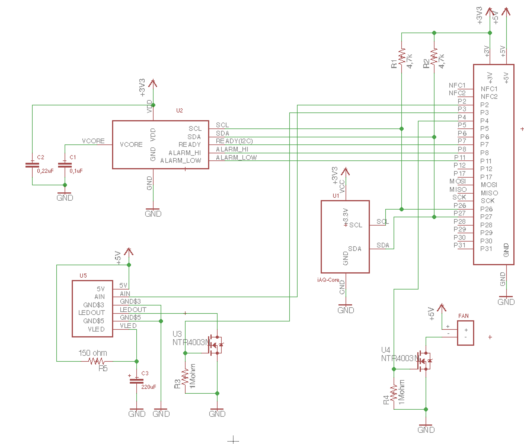
Parts list:
- U1. iAQ-Core CO2 sensor.
- U2. ChipCap 2 Temperature / humidity sensor.
- U3/U4. NTR4003N Mosfet.
- U5. DN7C3CA006 PM2.5 sensor
- R1/R2. 4k7 resistors
- R3/R4. 1M resistors
- C1. 0,1uF ceramic capacitor
- C2. 0,22uF ceramic capacitor
- C3. 220uF electrolytic capacitor
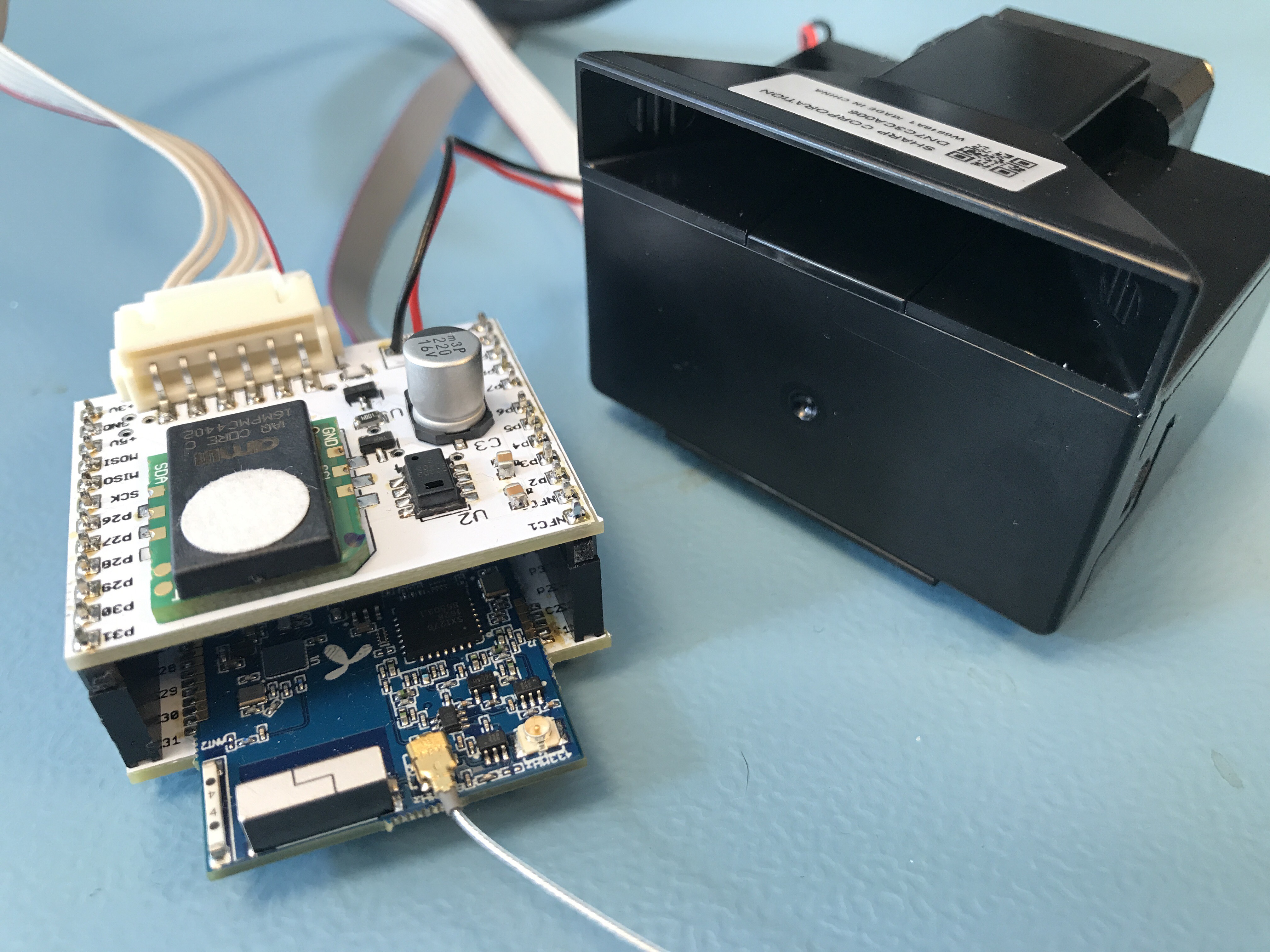
Finished sensor module.
Interfacing to the EE02
- P26: SCL (I2C)
- P27: SDA (I2C)
- P3: GPIO pin we will use to generate PWM for the PM2.5 sensor drive LED
- P4. GPIO pin we will use to control the PM2.5 sensor fan.
- P2. Analog input 0. This is the pin that will sense the sensor response voltage.
Doh! Moments
As usual - I made a mistake. The schematics are correct, but the board layout is flawed. When reading data from the temperature sensor, it reported ambient temperatures of 26C. I knew that this value was wrong, since it was tested in an air conditioned building, where the ambient temperature is stable at 21-22C. It turned out that the CO2 sensor has a heating element inside and that I had placed the temperature / humidity sensor too close to the CO2 sensor. After I moved the temperature sensor away from the CO2 sensor, the readings were as expected.